Tracked Robot

a tracked robot and track technology, applied in the field of robots, can solve the problems of high surface operation cost and risks, difficult welding, detection, polishing and cleaning of large wall surfaces of large ships, oil tanks, etc., and achieve the effects of preventing the track from derailing, limiting the movement space of the track, and preventing the track from slipping

Inactive Publication Date: 2021-01-14
GUANGDONG INST OF INTELLIGENT MFG
View PDF0 Cites 3 Cited by
  • Summary
  • Abstract
  • Description
  • Claims
  • Application Information

AI Technical Summary

Benefits of technology

The present invention has several technical benefits. First, baffles are placed on the outer sides of the driving wheels, which restricts the movement space of tracks and prevents them from derailing. Second, grooves are formed in the load bearing wheels to match with shifting teeth inside the tracks for transmission, preventing the load bearing wheels from slipping on the tracks. Third, buffering mechanisms are placed on the tensioning wheels to provide space for the tracks and to buffer them during tensioning. Fourth, attractive components are placed in the gaps between the convex platforms to provide attraction pressure for the robot and reduce robot-wall surface collisions, making the robot walk smoother. Fifth, the surfaces of the convex platforms are patterned to increase friction between the tracks and wall surface, improving the friction force.

Problems solved by technology

Aloft work such as welding, detection, polishing and cleaning for large wall surfaces of large ships, oil tanks, nuclear power plants and the like are difficult in the current industrial field.
Due to the smoothness and flatness of wall surfaces, manual operation is extremely difficult and low in efficiency, resulting in high surface operation costs and risks.
However, the phenomenon of chain disengaging is prone to occurring when robots bear large lateral stress according to traditional chain-type tracked structures.

Method used


Image

  • Tracked Robot
  • Tracked Robot

Examples


first embodiment

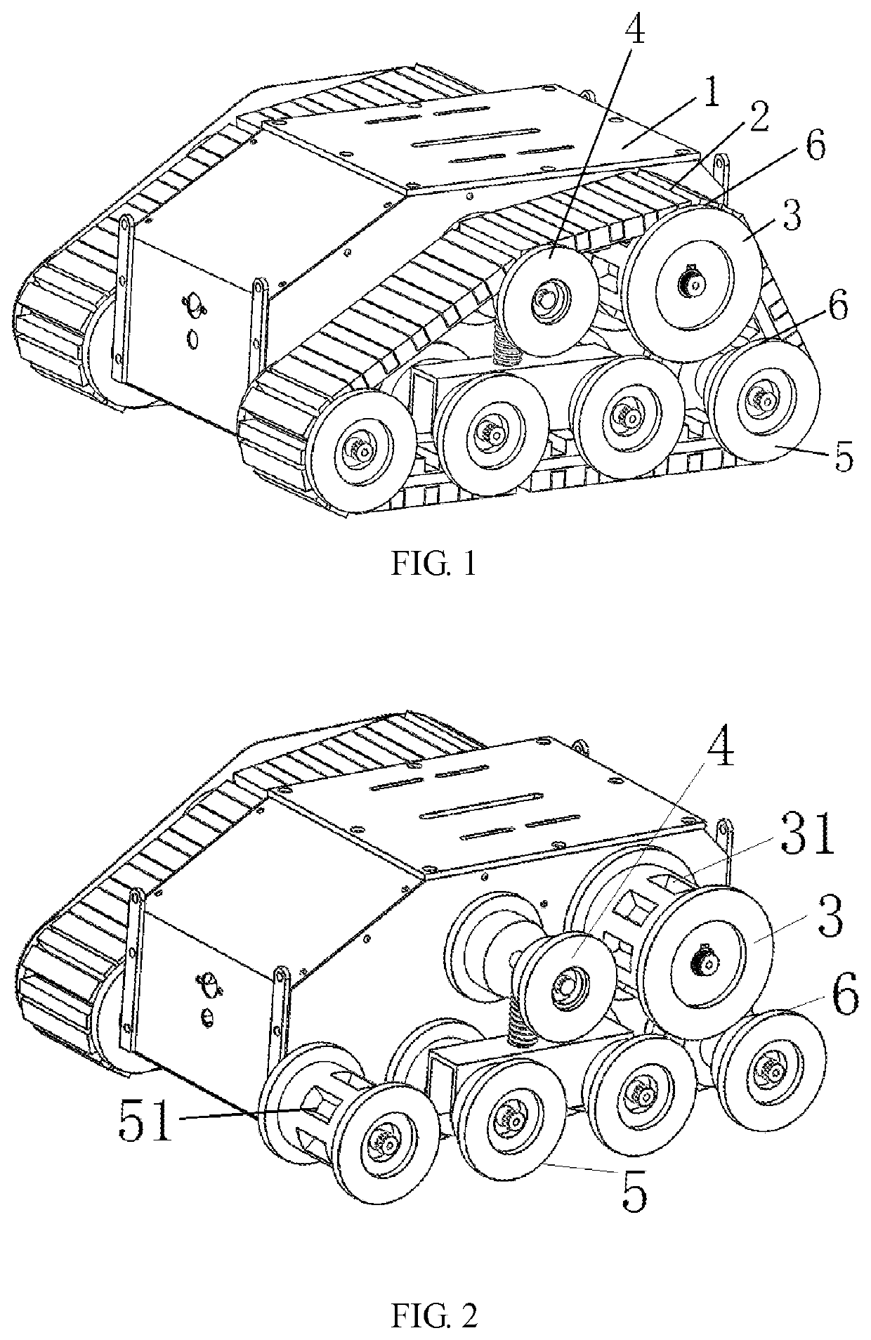
[0017]FIG. 1 is an overall structural view of a tracked robot of the present invention. As is shown in FIG. 1, a tracked robot comprises a rack 1, two track mechanisms and power components operating respectively in cooperation with the two track mechanisms. Each track mechanism comprises a track 2, a driving wheel 3, a tensioning wheel 4 and a plurality of load bearing wheels 5, wherein the driving wheel 3, the tensioning wheel 4 and the load bearing wheels 5 are sleeved with the track 2, the driving wheel 3, the tensioning wheel 4 and the load bearing wheels 5 are rotatably arranged on the track 1 respectively through a driving wheel axle, a tensioning wheel axle and load bearing wheel axles, the tensioning wheel 4 is used for tensioning the track 2, and the driving wheel 3 drives the tensioning wheel 4 and the load bearing wheels 5 to rotate through the track 2. Baffles are arranged on the outer sides of the driving wheels 3, the tensioning wheels 4 and the multiple load bearing w...

second embodiment

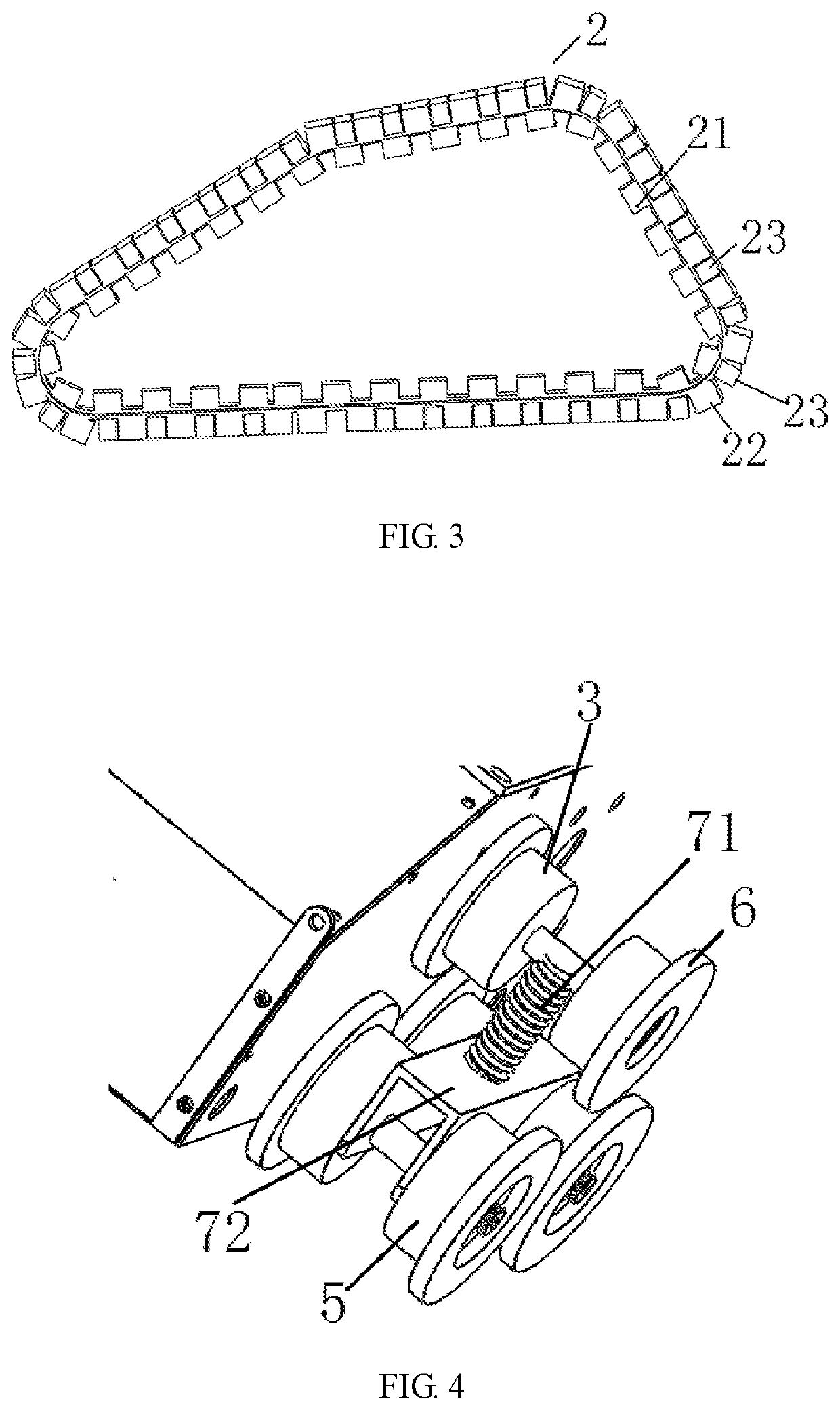
[0020]As for the aforesaid tracked robot, the second embodiment is different from the above embodiment in that the driving wheels 3 are provided with clamping grooves 31 matched with shifting teeth 21 inside the tracks 2 to drive the tracks 2 to achieve transmission, the load bearing wheels 5 on both sides of each track 2 are provided with grooves 51 (grooves in the load bearing wheel 5 on one side are not shown in the figures), the grooves 51 are matched with the shifting teeth 21 inside the tracks to achieve transmission, each tensioning wheel 3 and each of other multiple load bearing wheels 5 are respectively composed of two half side wheels, and baffles on the outer sides of the driving wheels 3, the tensioning wheels 4 and the load bearing wheels 5 can limit the movement of the tracks.

[0021]In this embodiment, the bearing wheels 5 on both sides of each track 2 are provided with the corresponding grooves 51, and the grooves 51 are matched with the shifting teeth 21 inside the tr...

third embodiment

[0022]As for the aforesaid tracked robot, the third embodiment is different from the above embodiments in that the driving wheels 3 are provided with clamping grooves 31 matched with shifting teeth 21 inside the tracks 2 to drive the tracks 2 to achieve transmission, each tensioning wheel 4 and each load bearing wheel 5 are respectively composed of two half side wheels (each load bearing wheel is composed of two half side wheels not shown in the figures), and baffles 6 on the outer sides of the driving wheels 3, the tensioning wheels 4 and the load bearing wheels 5 can limit the movement of the tracks.


PUM


Abstract

The tracked robot including a rack, two sets of track mechanisms and power components operating respectively in cooperation with the two sets of track mechanisms. Each set of track mechanism includes a track, a driving wheel, a tensioning wheel and a plurality of load bearing wheels, wherein the driving wheel, the tensioning wheel and the load bearing wheels are sleeved with the track, the tensioning wheel is used for tensioning the track, the driving wheel, the tensioning wheel and the load bearing wheels are rotatably arranged on the rack respectively through a driving wheel axle, a tensioning wheel axle and load bearing wheel axles, the driving wheel drives the tensioning wheel and the load bearing wheels to rotate through the track, baffles are arranged on the outer sides of the driving wheel, the tensioning wheel and the plurality of bearing wheels, and the track is embedded between the baffles.

Description

FIELD OF THE INVENTION[0001]The present invention relates to the field of robots, in particular to a tracked robot.BACKGROUND OF THE INVENTION[0002]Aloft work such as welding, detection, polishing and cleaning for large wall surfaces of large ships, oil tanks, nuclear power plants and the like are difficult in the current industrial field. Due to the smoothness and flatness of wall surfaces, manual operation is extremely difficult and low in efficiency, resulting in high surface operation costs and risks. Thus, a safe and reliable wall climbing robot is urgently needed for current engineering operation.[0003]At present, only tracked attractive robots have high load capacity and are stable in operation, safe and reliable. However, the phenomenon of chain disengaging is prone to occurring when robots bear large lateral stress according to traditional chain-type tracked structures. For this reason, it is urgently necessary to develop a chain disengaging prevention tracked robot. In con...

Claims


Application Information

Patent Timeline
Patent Type & Authority Applications(United States)
IPC IPC(8): B62D55/06B62D55/30B62D55/14B62D55/125
CPCB62D55/06B62D55/30B62D55/075B62D55/125B62D55/14B62D55/12
Inventor JIANG, XIAOMINGLIU, XIAOGUANGCAO, LICHAOZHANG, LIHE, LIANGZHOU, YONG
Owner GUANGDONG INST OF INTELLIGENT MFG
Why Eureka
Try Eureka