Vibration motor

a vibration motor and motor shaft technology, applied in the direction of control/drive circuits, mechanical energy handling, magnetic circuit shape/form/construction, etc., can solve the problems of less space available in the space of linear motors, difficulty in output wiring processes, and increased complexity of the output wiring process, so as to reduce friction and noise, improve positioning accuracy, and reduce the effect of structur

Active Publication Date: 2022-11-17
DELTA ELECTRONICS INC
View PDF7 Cites 0 Cited by
  • Summary
  • Abstract
  • Description
  • Claims
  • Application Information

AI Technical Summary

Benefits of technology

The vibration motor described in this disclosure has three position-limiting ribs on its internal surface, which restricts the movement of the magnetic ring to move only along its central axial line. This reduces the contact area between the magnetic ring and the position structure, resulting in decreased friction and noise. Additionally, the positioning accuracy of the motor is improved, which reduces the accuracy requirements of the parts. Furthermore, the bidirectional coil can be directly installed into the insulating housing without the need for an additional bobbin, reducing the number of parts and simplifying the assembly process.

Problems solved by technology

However, the linear motor is getting more and more compact, and less space therein is available.
The structure has a problem of space utilization, so that the space for winding being occupied or a multi-wire output arrangement may lead to a difficulty of output wiring process.
The positioning method of the central pin may cause noise when moving parts are in movement.
Therefore, elastic pieces or springs should be arranged for clamping the magnetic vibrator along an axial direction thereof, and additional material cost is caused.
Moreover, unexpected lateral vibrations may be caused.

Method used


Image

  • Vibration motor
  • Vibration motor
  • Vibration motor

Examples


Embodiment Construction

[0020]The technical contents of this disclosure will become apparent with the detailed description of embodiments accompanied with the illustration of related drawings as follows. It is intended that the embodiments and drawings disclosed herein are to be considered illustrative rather than restrictive.

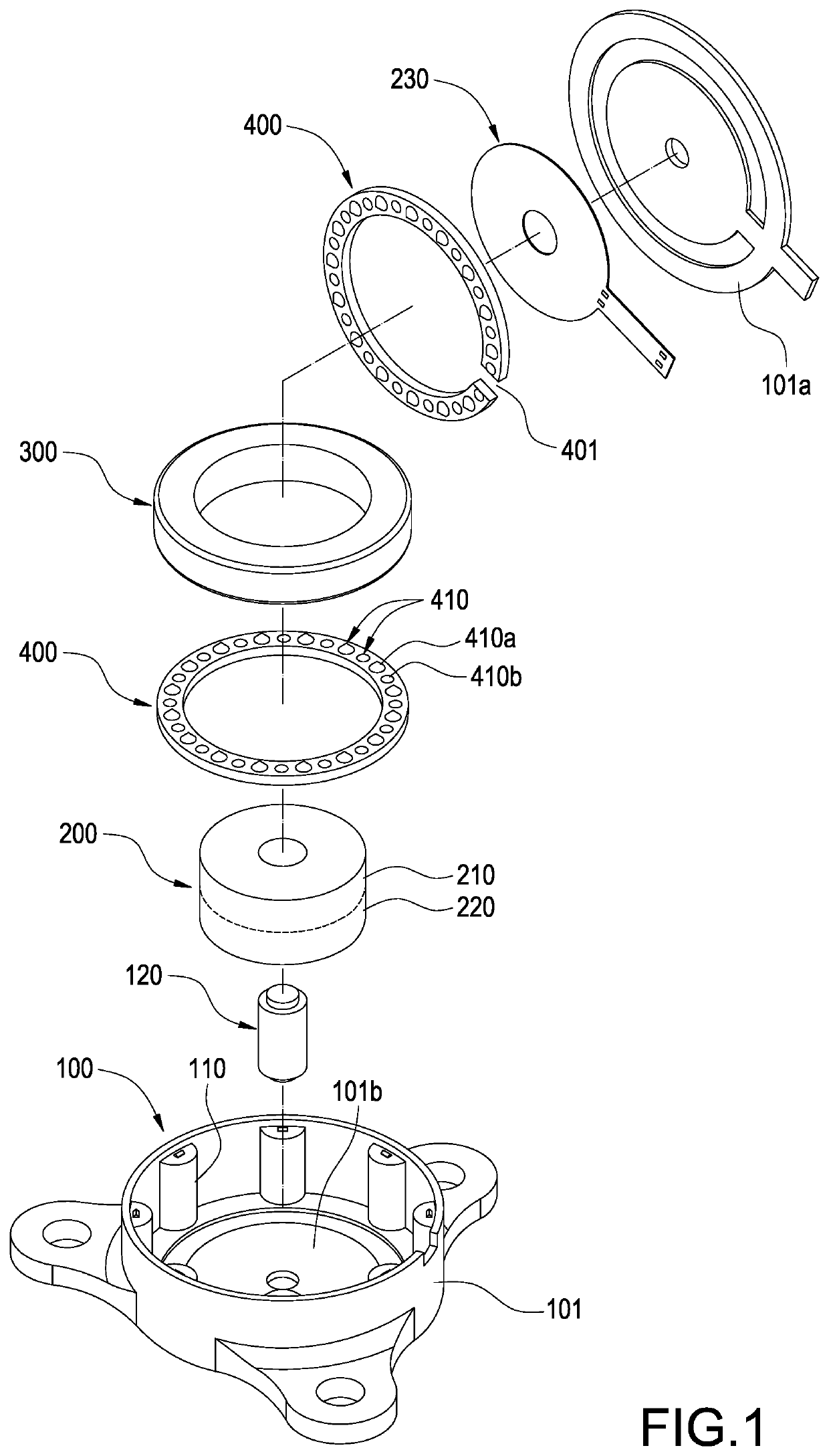
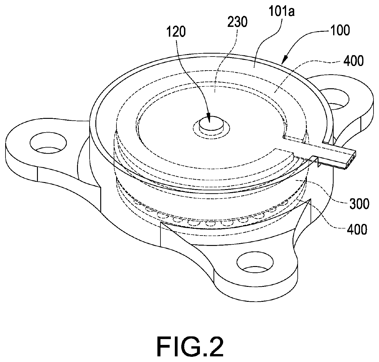
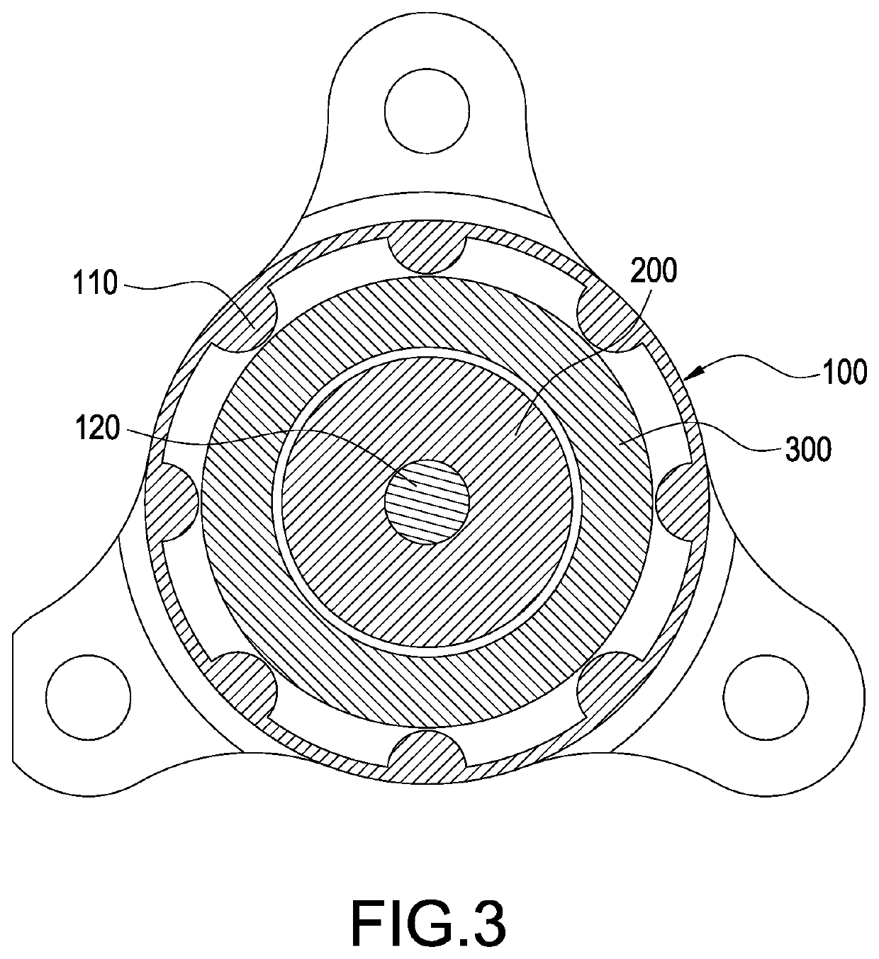
[0021]According to FIGS. 1 to 3, a vibration motor having insulating housing 100, a bidirectional coil 200, a magnetic ring 300 and a control circuit board 230 is provided in an embodiment of this disclosure.

[0022]The insulating housing 100 is of a cylindrical shape and has a cylinder 101 and a pair of end plates 101a / 101b closing two ends of the cylinder 101. In some embodiments, one of the end plates 101b and one end of the cylinder 101 are made in a one-piece form, and the other end plate 101a is detachably arranged on the other end of the cylinder 101. At least three position-limiting ribs 110 are protruded from an internal surface of the insulating housing 100, the respective pos...


PUM


Abstract

A vibration motor having an insulating housing, a bidirectional coil and a magnetic ring is provided. The insulating housing is of cylindrical shape and at least three position-limiting ribs are protruded from an internal surface thereof. Each position-limiting rib is extended parallel to a central axial line of the insulating housing. The insulating housing has a pair of end plates on two ends thereof. The end plates are made of insulating material. The bidirectional coil is accommodated in the insulating housing and spaced apart from the internal surface of the insulating housing. The magnetic ring is movably accommodated in the insulating housing, and the magnetic ring is arranged coaxially with the insulating housing to surround the bidirectional coil. The position-limiting ribs are disposed adjacent to the magnetic ring and surround an outer edge of the magnetic ring.

Description

BACKGROUNDTechnical Field[0001]This disclosure is related to a vibration motor and in particular to a vibration motor with noise suppression.Description of Related Art[0002]A related linear motor has a bobbin or at least two coils in order to excite a magnetic vibrator via bipolar coils for reciprocating. However, the linear motor is getting more and more compact, and less space therein is available. The structure has a problem of space utilization, so that the space for winding being occupied or a multi-wire output arrangement may lead to a difficulty of output wiring process.[0003]A related arrangement provides a housing having a metal frame as a part thereof, the magnetic vibrator is of annular shape and a central line thereof is usually positioned via components such as a center column, elastic piece, or spring. There are two configurations of the magnetic vibrator and the coils. If the magnetic vibrator is arranged in the coil, the magnetic vibrator is arranged to sleeve a cent...

Claims


Application Information

Patent Timeline
Patent Type & Authority Applications(United States)
IPC IPC(8): H02K33/16H02K7/06H02K1/18
CPCH02K33/16H02K7/063H02K1/182H02K5/08H02K5/22H02K33/02H02K11/30H02K3/28H02K5/24H02K33/12H02K1/06
Inventor CHEN, LI-CHUNTSAI, MING-CHIHCHEN, CHIEH-CHENG
Owner DELTA ELECTRONICS INC
Why Eureka
Try Eureka