
Device for filling and removing a lubricant at a housing

Active Publication Date: 2021-01-14
ZF FRIEDRICHSHAFEN AG
View PDF0 Cites 1 Cited by
  • Summary
  • Abstract
  • Description
  • Claims
  • Application Information

AI Technical Summary

Benefits of technology

The proposed filling and draining device for a lubricant system has a valve that can adjust the flow of lubricant during filling and draining. The valve has a valve element, such as a ball, that can move to different positions to control the aperture width. This allows for a larger volume flow of lubricant during filling and a smaller volume flow during draining. The valve can be fitted in a space-saving manner and is protected against outside influences. The lubricant line forms a main pressure line that is connected to the main pressure line of the transmission. This ensures that the pressure level in the lubricant system is constant and prevents damage to the components. The valve can be controlled to adjust the pressure level and protect the components from damage.

Problems solved by technology

Here, the problem arises that on the one hand as large a volume flow of lubricant as possible should flow into the housing during filling in order to keep the filling time as short as possible.
That represents a possible source of error.

Method used


Image

  • Device for filling and removing a lubricant at a housing

Examples


Embodiment Construction

[0035]In the figures, the same or at least functionally equivalent components and elements are denoted by identical indexes.

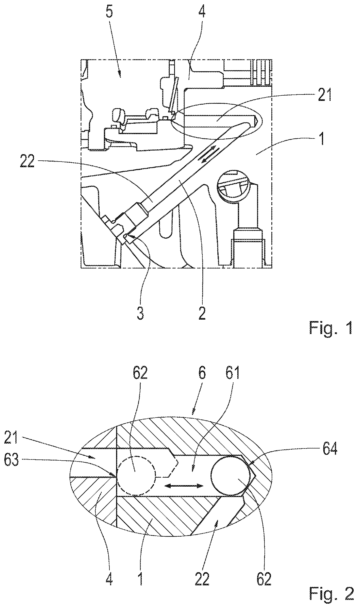
[0036]FIG. 1 shows a section through a transmission housing 1 of a motor vehicle known as such. Through the transmission housing 1 there extends a lubricant line 2 in the form of a duct arranged inside the wall of the transmission housing 1.

[0037]Outside the transmission housing 1 the lubricant line 2 opens into a connection 3 for a PTO that can be arranged on the transmission housing 1. Thus, on the transmission housing 1 in the area of the exterior outlet of the lubricant line 2 an area of the housing is provided for arranging the PTO on the transmission housing 1, for example an appropriately shaped flange and threaded bores for fixing the PTO. In this part of the housing there is also, in particular, an opening such as a housing window through which the PTO can extend into the transmission housing 1 and through which drive power can be tapped off from the t...


PUM


Abstract

A filling and draining device for filling lubricant into and draining lubricant out of a housing (1), having a lubricant line (2, 21, 22) through which the lubricant passes into the housing (1), during filling, and through which the lubricant passes when the lubricant is drained from the housing (1). The housing (1) has a valve (6) through which the lubricant flows during filling and draining such that, for filling, the valve (6) adopts a first aperture width for the lubricant and, for draining, the valve (6) adopts a second aperture width for the lubricant.

Description

[0001]This application claims priority from German patent application serial no. 10 2019 210 267.0 filed Jul. 11, 2019.FIELD OF THE INVENTION[0002]The invention relates to a filling and draining device for filling a lubricant into and draining it out of a housing. It also relates to a transmission housing with such a filling and draining device. Furthermore, the invention relates to a method for producing a transmission with an auxiliary power take-off and with such a transmission housing.BACKGROUND OF THE INVENTION[0003]Technical devices are often lubricated by means of a lubricant and if necessary also cooled thereby. So that the lubricant cannot inadvertently escape, housings are provided for the devices. During the production of the device its housing is filled with the lubricant. This can be done by way of a lubricant line. Thus, during filling the lubricant passes into the housing by way of the lubricant line. Through the lubricant line it is also often possible, if needs be, ...

Claims


Application Information

Patent Timeline
IPC IPC(8): F16H57/04F01M11/04F16H57/02
CPCF16H57/0408F16H57/02F01M11/0458F16N31/00F16N2210/12F01M2011/0433F16H2200/0004B60K25/06
Inventor FIESEL, SASCHA
Owner ZF FRIEDRICHSHAFEN AG
Learn More