Radar range ambiguity resolution using multi-rate sampling

Pending Publication Date: 2021-01-14
GM GLOBAL TECH OPERATIONS LLC
View PDF53 Cites 1 Cited by
  • Summary
  • Abstract
  • Description
  • Claims
  • Application Information

AI Technical Summary

Benefits of technology

[0005]The radar circuit uses an ADC with multiple different sampling frequencies to estimate a true range to a radar target. As will be appreciated by one of ordinary skill in the art, the maximum detection range of a CW radar circuit increases with the sampling frequency of the ADC. However, a high-frequency ADC has certain potential disadvantages, including added complexity and cost, higher power demands, and the potential to generate more heat relative to lower-frequency ADCs. The multiple ADC sampling frequencies employed in accordance with the present teachings therefore provide an extended detection range comparable to a higher-frequency ADC while maintaining the cost and complexity advantages of low-frequency ADC sampling.
[0006]An effect of using the disclosed multi-sampling rat

Problems solved by technology

However, a high-frequency ADC has certain potential disadvantages, including added complexity and cost, higher power demands, and the potent

Method used


Image

  • Radar range ambiguity resolution using multi-rate sampling
  • Radar range ambiguity resolution using multi-rate sampling
  • Radar range ambiguity resolution using multi-rate sampling

Examples


Embodiment Construction

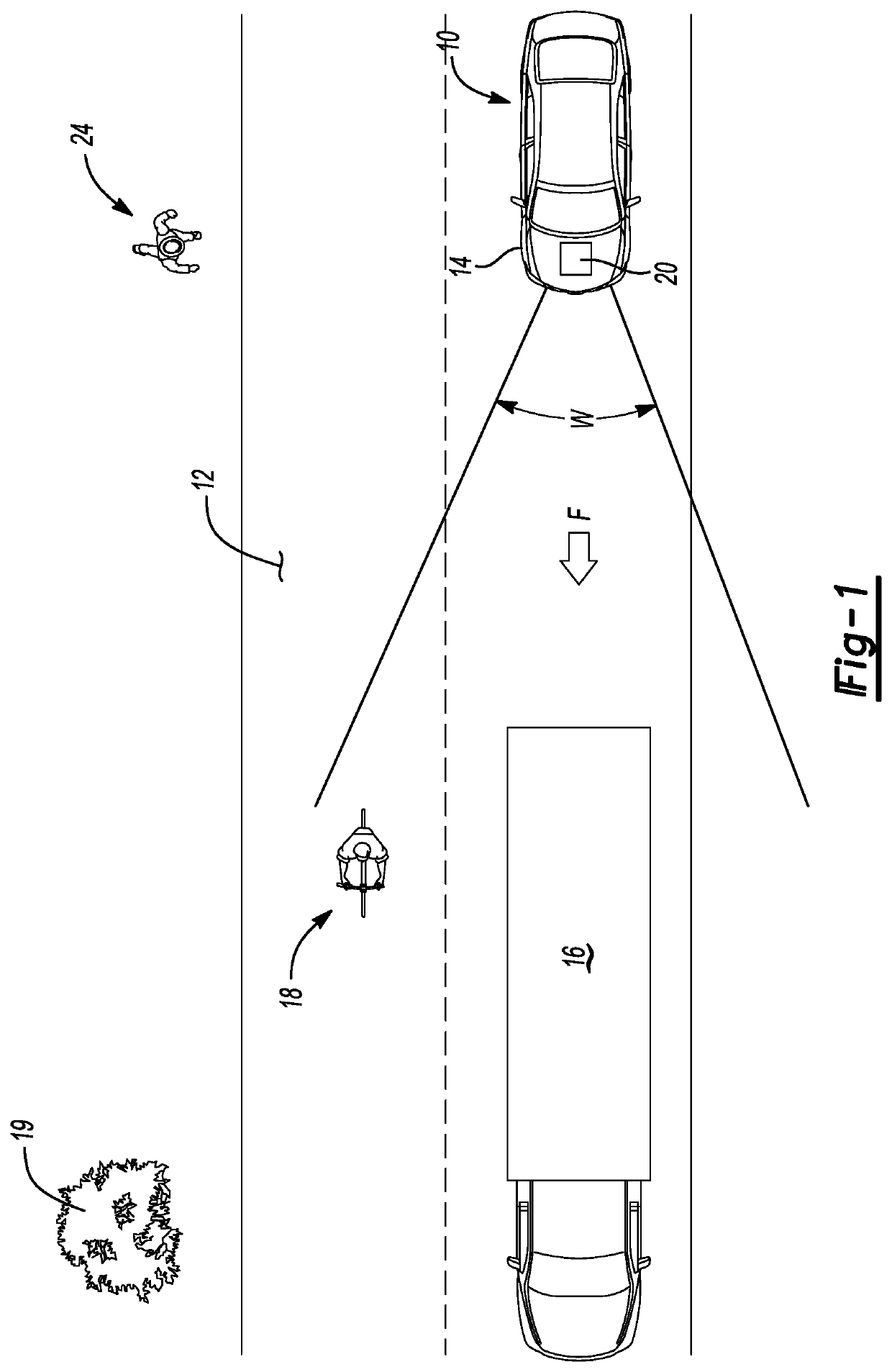
[0027]Referring to the drawings, wherein like reference numbers refer to like components, a host system in the form of an exemplary host vehicle 10 is depicted schematically in FIG. 1. The host vehicle 10 is depicted in the illustrated embodiment as a motor vehicle. However, other vehicles may benefit from the present teachings, including but not limited to watercraft, aircraft, and rail vehicles, with the teachings being applicable as well to robots and other mobile platforms. For illustrative consistency, the host vehicle 10 will be described hereinafter in the context of a ground-based vehicle without limiting the scope of the disclosure to such an embodiment.

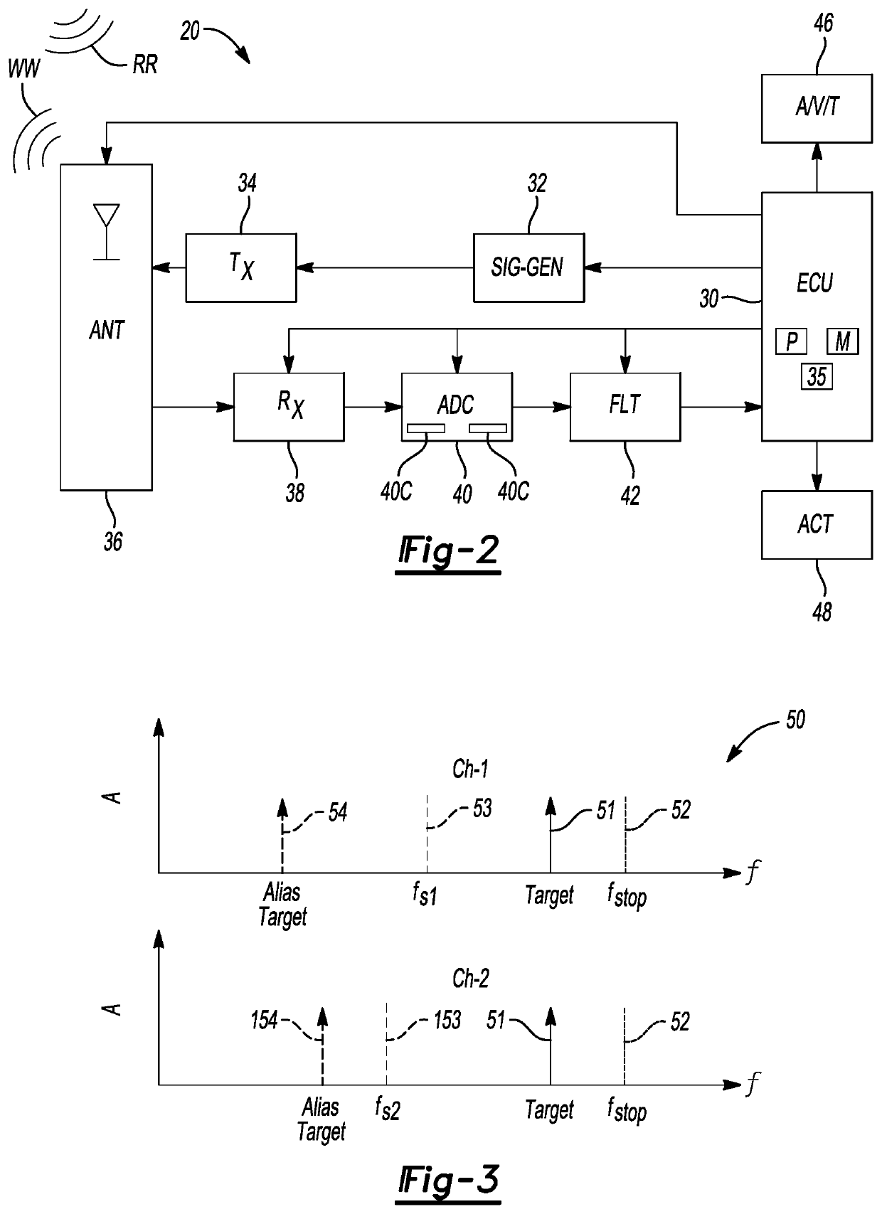
[0028]The host vehicle 10 includes a vehicle body 14 and a radar circuit 20, with an example embodiment of the radar circuit 20 being described in further detail below with reference to FIG. 2. The host vehicle 10, when optionally configured as a motor vehicle as shown, travels in the general direction of arrow F along a roa...


PUM


Abstract

A radar circuit for use with a vehicle or other host system includes a radio frequency (RF) signal generator, an RF antenna connected to the signal generator configured to transmit an RF waveform toward a radar target and receive a radar return signature reflected therefrom, and an analog-to-digital converter (ADC) in communication with the antenna and having a different sampling frequencies. The ADC may have multiple channels outputting sampled radar return signature data at the different sampling frequencies. An ECU is in communication with the ADC to receive the sampled radar return signature data from the ADC, generate a set of range hypotheses describing a possible range from the host system to the radar target, select a correct range hypothesis, and execute a control action using the correct range hypothesis. The correct range hypothesis corresponds to a true range to the radar target.

Description

INTRODUCTION[0001]Radar systems are often employed to assist in the real-time detection and localization of obstacles in proximity to a host system. For example, a radar system may be used aboard a vehicle to detect other vehicles, pedestrians, or stationary objects. Radar is also an enabling technology for autonomous or semi-autonomous control of various driver-assist subsystems. Examples of such driver-assist subsystems include adaptive cruise control, automatic lane-changing / lane-keeping, automatic braking or steering, and backup assistance subsystems. Radar-based obstacle detection is also used to enhance overall situational awareness of a vehicle operator, e.g., by triggering and displaying timely alerts.[0002]In a typical radar system, pulsed or continuous-wave (CW) radio frequency (RF) energy is transmitted as radio waves in a predetermined scanning direction, such as a forward, lateral, and / or rear direction relative to a host system. If the transmitted RF energy encounters ...

Claims


Application Information

Patent Timeline
IPC IPC(8): G01S13/93G01S7/03
CPCG01S13/931G01S7/03G01S2013/9342G01S2013/9321G01S2013/9346G01S2013/9314G01S7/352G01S2013/9318G01S2013/93185G01S13/08
Inventor LONGMAN, ORENBILIK, IGAL
Owner GM GLOBAL TECH OPERATIONS LLC
Why Eureka
Try Eureka