Sprayer boom suspension assembly

a technology of suspension assembly and boom, which is applied in the field of agricultural crop sprayers, can solve the problems of uneven spraying of fields, acceleration or deceleration of vehicles, and significant portion of the boom unsupported when fully extended, so as to limit the extent of yaw and pitch oscillation, and improve the effectiveness and performance of the cylinders.

Pending Publication Date: 2021-01-21
AGCO INT GMBH
View PDF14 Cites 2 Cited by
  • Summary
  • Abstract
  • Description
  • Claims
  • Application Information

AI Technical Summary

Benefits of technology

[0013]In one embodiment each of the first and second damping means further comprises a bell crank pivotally mounted to the chassis, wherein the damping cylinder is connected between the chassis and a first arm of the bell crank, and a tie rod is connected between a second arm of the bell crank and the boom support frame. The bell crank permits the damping cylinders to be mounted with more of a vertical component which improves the effectiveness and performance of the cylinders.
[0014]The damping means preferably further comprises one or more springs or cushions secured to the chassis to act upon the bell crank and limit the extent of the yaw and pitch oscillations and bias the support frame back into a neutral position.

Problems solved by technology

This leaves a significant portion of the boom unsupported when fully extended and relies on only the rigidity of the boom structure to remain in position.
Excessive yaw movement can result in uneven application of the spray to areas of the field.
‘Pitch’ is movement of the entire boom about a lateral or transverse axis and typically results from acceleration or deceleration of the vehicle.
Excessive yaw movement can also result in uneven spray application.
‘Roll’ is movement of the boom around a longitudinal axis and typically results from the vehicle being driven over uneven terrain.
Left uncontrolled, excessive roll can result in the extremities of the boom striking the ground thus risking damage to both the boom and the crop.
Oscillations in any direction can increase in amplitude to the extent where the machine must be stopped and restarted leading to inconvenience for the operator and an inefficient working approach.
Attempts have been made to control the various oscillations in a boom resulting in rather complex suspension and damping systems.
Although capable of controlling movements of the boom, known systems comprise many components adding to the overall weight and complexity of the assembly.

Method used


Image

  • Sprayer boom suspension assembly
  • Sprayer boom suspension assembly
  • Sprayer boom suspension assembly

Examples


Embodiment Construction

[0027]The invention will now be described in the following detailed description with reference to the drawings, wherein preferred embodiments are described in detail to enable practice of the invention. Although the invention is described with reference to these specific preferred embodiments, it will be understood that the invention is not limited to these preferred embodiments. But to the contrary, the invention includes numerous alternatives, modifications and equivalents as will become apparent from consideration of the following detailed description.

[0028]Reference to terms such as longitudinal, transverse and vertical are made with respect to a longitudinal vehicle axis which is parallel to a normal forward direction of travel.

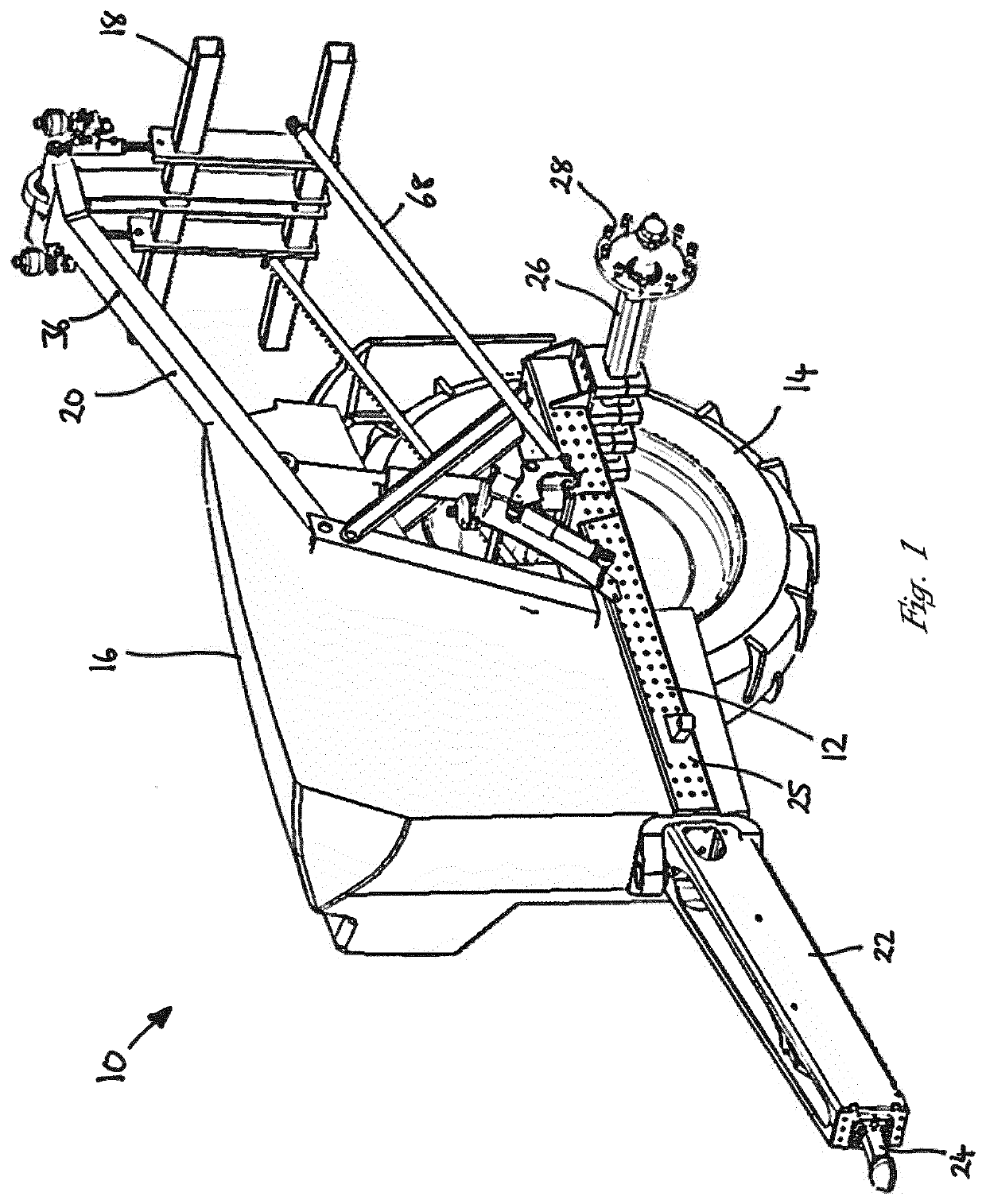
[0029]With reference to FIG. 1 a pull-type, or trailed, sprayer 10 comprises a chassis 12, ground engaging wheels 14, a storage tank 16 and a boom support frame 18 suspended from a lift arm assembly 20. It should be appreciated that the storage tank 16 i...


PUM


Abstract

A boom suspension assembly for an agricultural sprayer having a chassis, a lift arm assembly mounted to the chassis, and a boom support frame pendulously suspended from the lift arm assembly. Springs and dampers between the chassis and the boom support frame control pitch and yaw movement of the boom support frame away from a neutral position. The lift arm assembly, boom support frame and dampers provide a four-bar linkage which maintains the boom support frame in a steady alignment when raised and lowered.

Description

FIELD OF INVENTION[0001]The invention relates to agricultural crop sprayers and particularly to the mounting of a transversely-extending sprayer boom to a chassis of a sprayer machine in a manner which permits raising and lowering of the boom, and also yaw, pitch and roll movement of the boom.BACKGROUND[0002]Agricultural sprayers are used by farmers and contractors to apply pesticides and other nutrient-containing solutions to crop fields. Sprayer machines can be mounted to, or towed by, a tractor or other suitable vehicle, or may be self-propelled with an integrated means of propulsion and a driver's cab. The sprayer machine typically includes a storage tank for the liquid to be applied, the tank being filled as required by the operator. However, it is also known to supply the liquid to the sprayer machine via a supply pipe connected to a remote bowser for example.[0003]The liquid is applied to the field by a number of liquid application devices, commonly spray nozzles, which are m...

Claims


Application Information

Patent Timeline
Patent Type & Authority Applications(United States)
IPC IPC(8): B05B9/06
CPCB05B9/06A01M7/0053A01M7/0057
Inventor HIDDEMA, JORIS JAN
Owner AGCO INT GMBH
Why Eureka
Try Eureka