Sensor system
- Summary
- Abstract
- Description
- Claims
- Application Information
AI Technical Summary
Benefits of technology
Problems solved by technology
Method used
Image

Examples
Embodiment Construction
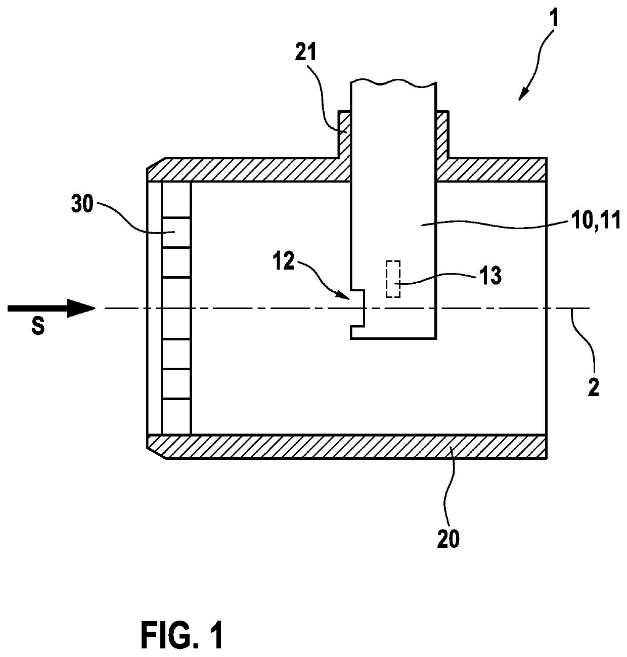
[0021]FIG. 1 shows a schematic cross section through a sensor system 1 in accordance with an example embodiment of the present invention. Sensor system 1 includes a flow tube 20, which is designed, for example, as a cylindrical tube or includes, for example, at least one section in the form of a cylindrical tube. Flow tube 20 may be installed as part of an intake air tract in a motor vehicle. Flow tube 20 has a center axis 2, which extends through the center point of the circular cross section of flow tube 20. Flow tube 20 may be made from plastic, for example. Intake air flows in a main flow direction S in flow tube 20. Main flow direction S is defined as the direction in which the intake air flows from one end of the flow tube to the other end of the flow tube in the main axis without local flows or microturbulence formations being observed. In a cylindrical tube, the main flow direction always extends in the direction of the center axis of the cylindrical tube.
[0022]Furthermore, ...
PUM
 Abstract
Description
Claims
Application Information
 - R&D Engineer
- R&D Manager
- IP Professional
- Industry Leading Data Capabilities
- Powerful AI technology
- Patent DNA Extraction
Browse by: Latest US Patents, China's latest patents, Technical Efficacy Thesaurus, Application Domain, Technology Topic.
© 2024 PatSnap. All rights reserved.Legal|Privacy policy|Modern Slavery Act Transparency Statement|Sitemap