Radical assist ignition plasma system and method

a plasma system and assist technology, applied in the direction of electrical equipment, basic electric elements, electric discharge tubes, etc., can solve the problems of undesired damage to the core material, high power to ignite the plasma, and deviation from desired patterns, so as to reduce the damage to the material

Active Publication Date: 2021-01-21
ASM IP HLDG BV
View PDF0 Cites 162 Cited by
  • Summary
  • Abstract
  • Description
  • Claims
  • Application Information

AI Technical Summary

Benefits of technology

[0011]Various embodiments of the present disclosure relate to plasma-assisted methods and apparatus. While the ways in which various embodiments of the present disclosure address drawbacks of prior methods and systems are discussed in more detail below, in general, various embodiments of the disclosure provide improved methods that can be used to ignite a plasma within a reaction chamber. Various techniques described herein provide reliable methods for igniting a plasma within a reaction chamber and / or methods for reducing damage to material (e.g., patterned material, such as photoresist) on a substrate surface.

Problems solved by technology

This excess photoresist can cause deviations from desired patterns that are transferred from the photoresist to an underlying layer during a subsequent etching process.
Unfortunately, some conditions can include relatively high power to ignite the plasma.
The high-power conditions may cause undesired damage to the core material during the plasma ignition step.
Further, because of its dependence on other factors, typical plasma ignition processes can be relatively unstable and non-versatile.

Method used


Image

  • Radical assist ignition plasma system and method
  • Radical assist ignition plasma system and method
  • Radical assist ignition plasma system and method

Examples


Embodiment Construction

[0026]Although certain embodiments and examples are disclosed below, it will be understood by those in the art that the invention extends beyond the specifically disclosed embodiments and / or uses of the invention and obvious modifications and equivalents thereof. Thus, it is intended that the scope of the invention disclosed should not be limited by the particular disclosed embodiments described below.

[0027]The present disclosure generally relates to plasma-assisted methods and apparatus. As described in more detail below, exemplary methods can be used to facilitate plasma ignition within a reaction chamber; reduce damage, e.g., during a plasma ignition process, to material on a substrate surface; improve material removal rate uniformity across a surface of a substrate; and the like. The methods and apparatus described herein can be used to trim features on a substrate surface.

[0028]In this disclosure, “gas” may include material that is a gas at room temperature and pressure, a vapo...


PUM


Abstract

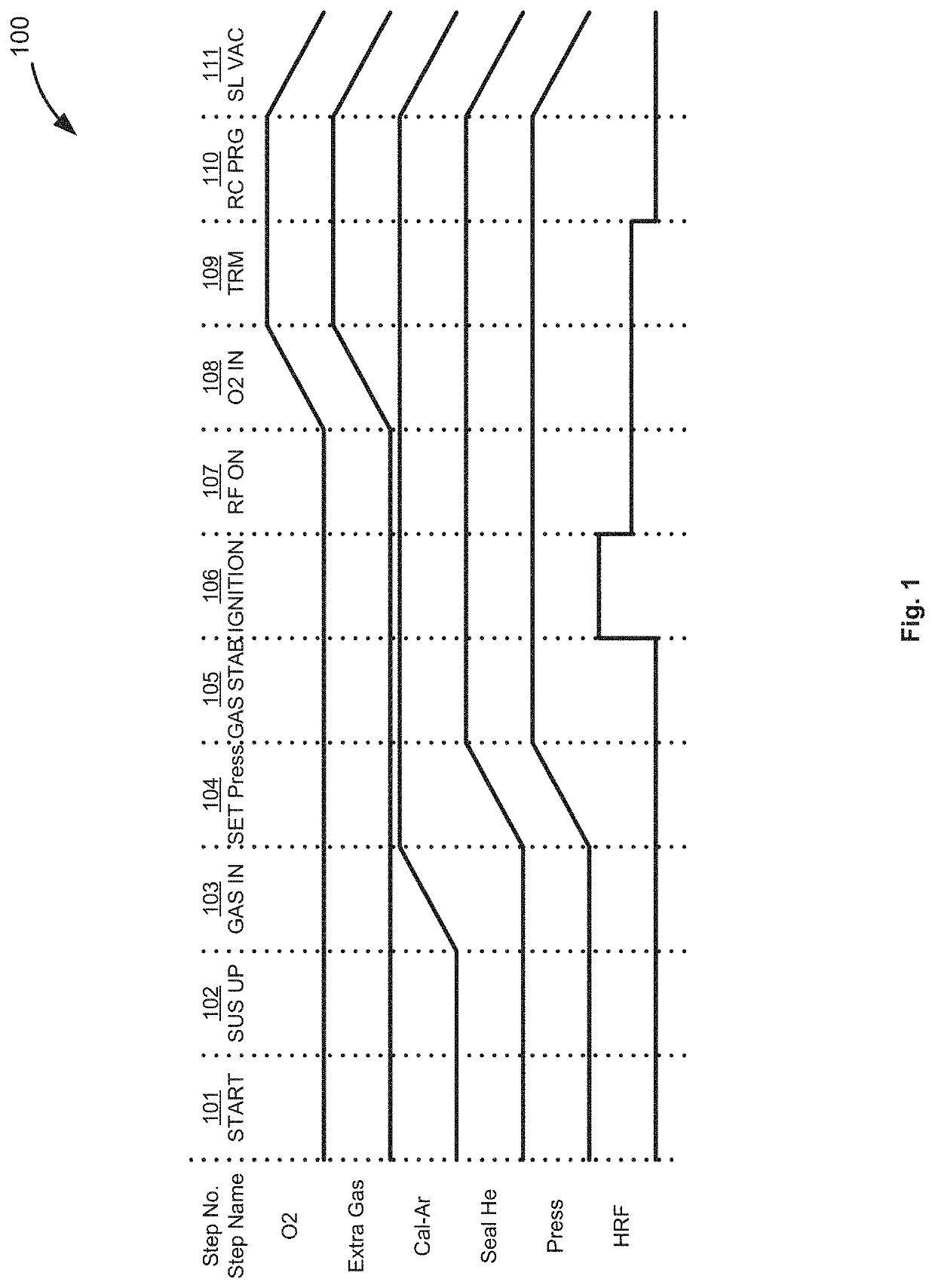
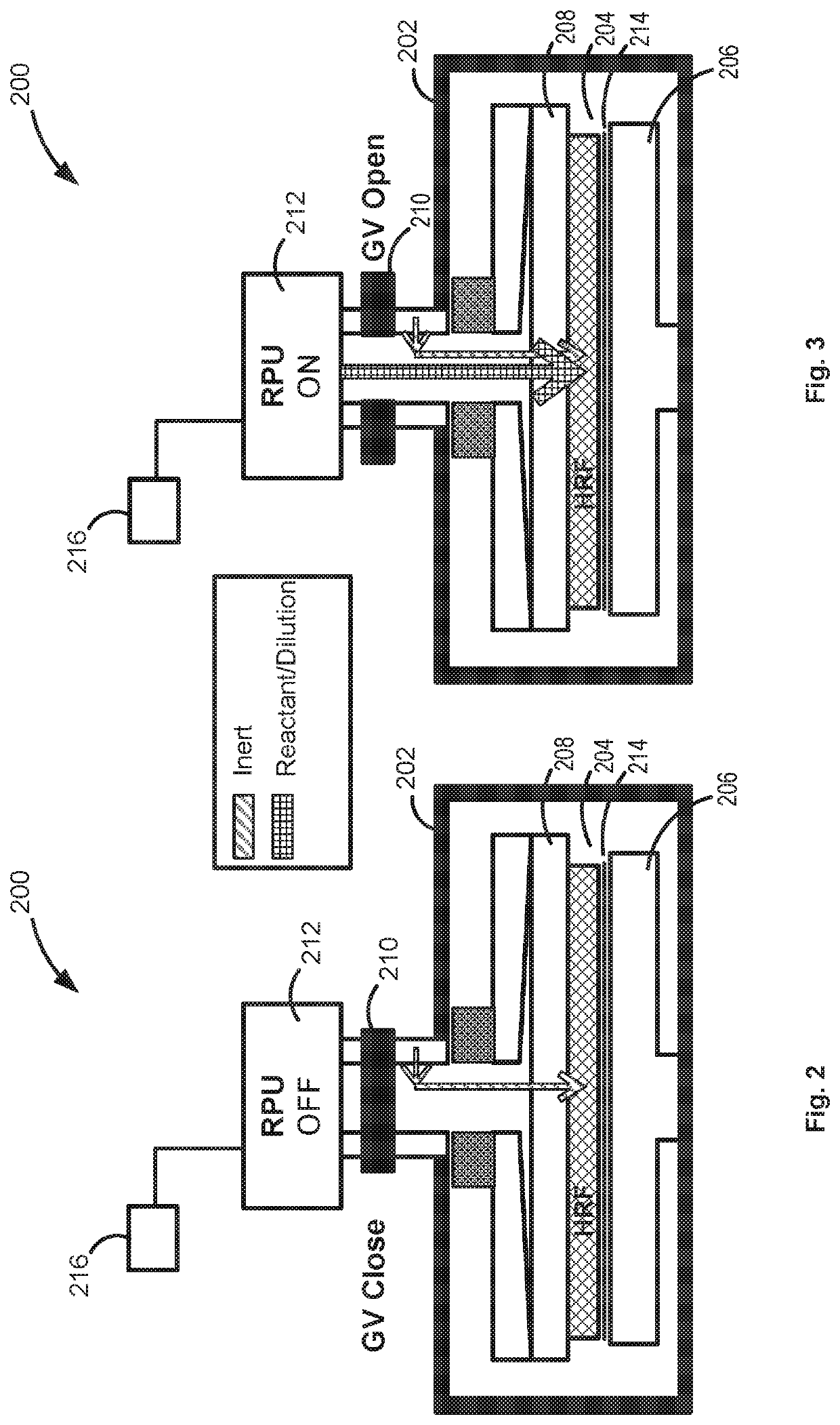
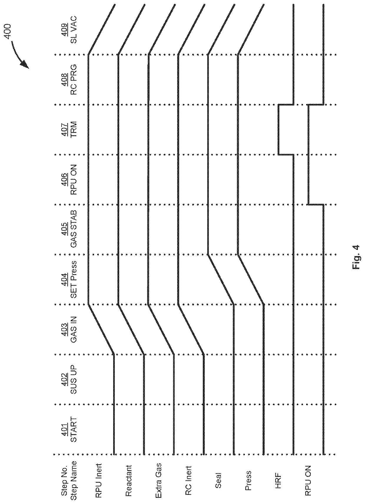
Plasma-assisted methods and apparatus are disclosed. The methods and apparatus can be used to provide activated species formed in a remote plasma unit to a reaction chamber to assist ignition of a plasma within a reaction chamber coupled to the remote plasma unit.

Description

CROSS-REFERENCE TO RELATED APPLICATIONS[0001]This application claims the benefit of U.S. Provisional Application No. 62 / 875,321, filed on Jul. 17, 2019, in the United States Patent and Trademark Office, the disclosure of which is incorporated herein in its entirety by reference.FIELD OF INVENTION[0002]The present disclosure generally relates to methods of forming device structures and to systems for forming the structures. More particularly, the disclosure relates to methods of using a plasma to form the devices and to systems with plasma reactors.BACKGROUND OF THE DISCLOSURE[0003]During the manufacture of electronic devices, fine patterns of features can be formed on a surface of a substrate by patterning the surface of the substrate and etching material from the substrate surface using, for example, plasma-assisted etching processes. As a density of devices on a substrate increases, it becomes increasingly desirable to form features with smaller dimensions.[0004]Photoresist is oft...

Claims


Application Information

Patent Timeline
Patent Type & Authority Applications(United States)
IPC IPC(8): H01L21/67H01L21/027H01L21/033H01L21/311H01J37/32
CPCH01L21/67069H01L21/0273H01L21/0337H01J2237/334H01L21/31138H01J37/32357H01J37/32422H01L21/31122H01J37/3053H01L21/67253H01L21/3065H01L21/3081H01L21/3086H01L21/0332
Inventor SEKIGUCHI, HIROO
Owner ASM IP HLDG BV
Why Eureka
Try Eureka