X-ray computed tomography apparatus with scanner function

a computed tomography and function technology, applied in the field of x-ray computed tomography apparatuses with a scanner function, can solve the problems of increasing equipment installation space and purchasing cost, and achieve the effect of reducing equipment purchase cost and installation space, and not significantly increasing costs

Active Publication Date: 2021-02-04
RAY
View PDF0 Cites 1 Cited by
  • Summary
  • Abstract
  • Description
  • Claims
  • Application Information

AI Technical Summary

Benefits of technology

[0029]According to another aspect of the present invention, there is provided an X-ray computed tomography apparatus with a scanner function, including: a vertical frame; a patient support arm provided below the vertical frame; a horizontal support arm extending horizontally from a top portion of the vertical frame; a rotary arm drive unit provided at an end of the horizontal support arm; a horizontal rotation arm provided horizontally below the rotary arm drive unit to rotate 360 degrees; an X-ray source provided at one end of the horizontal rotation arm; and an X-ray detector provided at the other end of the horizontal rotation arm to face the X-ray source, wherein the X-ray source is composed of a dual focus type X-ray source capable of emitting both a micro CT imaging X-ray and a general CT imaging X-ray from one tube, so that the apparatus can perform both a micro CT imaging operation and a general CT imaging operation.
[0030]According to the X-ray computed tomography apparatus of the present invention, it is possible to perform both a micro CT imaging operation of imaging a small object at a high resolution and a general CT imaging operation of imaging a part of a body of a patient.
[0031]Furthermore, it is possible to reduce equipment purchase cost and installation space, because both the micro CT imaging operation and the general CT imaging operation can be performed in one X-ray computed tomography apparatus.
[0032]In addition, it is possible to perform both the micro CT imaging operation and the general CT imaging operation without significantly increasing costs.

Problems solved by technology

This poses a problem in that the purchase cost is increased and the installation space of the equipment is increased.

Method used


Image

  • X-ray computed tomography apparatus with scanner function
  • X-ray computed tomography apparatus with scanner function
  • X-ray computed tomography apparatus with scanner function

Examples


first embodiment

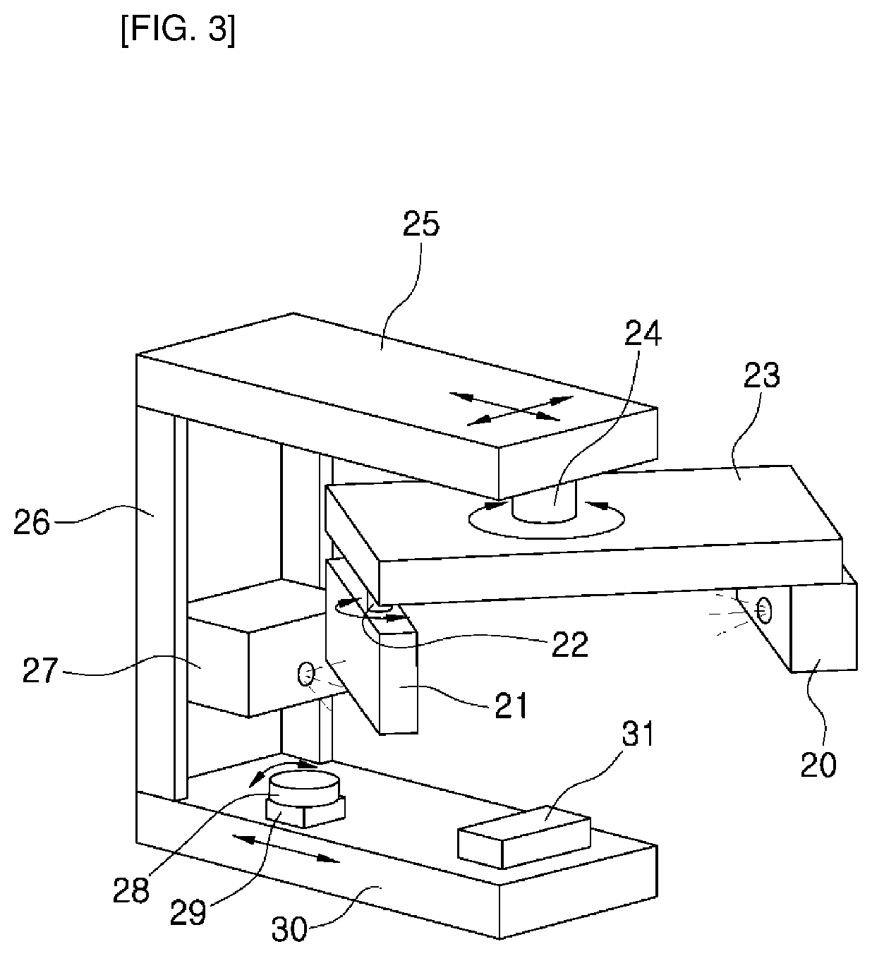
[0043]FIGS. 3 to 5 show an X-ray computed tomography (CT) apparatus according to a first embodiment of the present invention. Referring to FIG. 3, the X-ray CT apparatus with a scanner function according to the first embodiment of the present invention includes: a vertical frame 26; a patient support arm 30 provided below the vertical frame 26; a horizontal support arm 25 extending horizontally from a top portion of the vertical frame 26; a rotary arm drive unit 24 provided at an end of the horizontal support arm 25; a horizontal rotation arm 23 provided horizontally below the rotary arm drive unit 24 to rotate 360 degrees; a general CT imaging X-ray source 20 provided at one end of the horizontal rotation arm 23; and an X-ray detector provided at the other end of the horizontal rotation arm 23 to face the general CT imaging X-ray source 20, wherein a micro CT imaging X-ray source 27 is further provided on the vertical frame 26, a rotary table 28 for seating and rotating an object t...

second embodiment

[0060]FIG. 6 shows an X-ray CT apparatus according to a second embodiment of the present invention. The X-ray CT apparatus according to the second embodiment of the present invention includes two micro CT imaging X-ray sources, each of which is employed in the first embodiment.

[0061]That is, as shown in FIG. 6, a first X-ray source 34 and a second X-ray source 35 for performing a micro CT imaging operation by irradiating X-rays having different focuses are provided on the vertical frame 10 employed in the first embodiment.

[0062]According to the second embodiment of the present invention, there is an advantage that it is possible to perform a micro CT imaging for various objects.

[0063]Other matters are the same as those of the first embodiment described above, and the redundant description thereof will be omitted.

third embodiment

[0064]FIGS. 7 to 9 show an X-ray computed tomography (CT) apparatus according to a third embodiment of the present invention. Referring to FIG. 7, the X-ray CT apparatus with a scanner function according to the third embodiment of the present invention includes: a vertical frame 26; a patient support arm 30 provided below the vertical frame 26; a horizontal support arm 25 extending horizontally from a top portion of the vertical frame 26; a rotary arm drive unit 24 provided at an end of the horizontal support arm 25; a horizontal rotation arm 23 provided horizontally below the rotary arm drive unit 24 to rotate 360 degrees; an X-ray source 20 provided at one end of the horizontal rotation arm 23; and an X-ray detector provided at the other end of the horizontal rotation arm 23 to face the X-ray source, wherein the X-ray source is composed of a dual focus type X-ray source 36 capable of emitting both a micro CT imaging X-ray and a general CT imaging X-ray from one tube.

[0065]That is,...


PUM

PropertyMeasurementUnit
CT imagingaaaaaaaaaa
CTaaaaaaaaaa
imagingaaaaaaaaaa

Abstract

An X-ray computed tomography apparatus with a scanner function includes a vertical frame, a patient support arm provided below the vertical frame, a horizontal support arm extending horizontally from a top portion of the vertical frame, a rotary arm drive unit provided at an end of the horizontal support arm, a horizontal rotation arm provided horizontally below the rotary arm drive unit to rotate 360 degrees, a general CT imaging X-ray source provided at one end of the horizontal rotation arm, and an X-ray detector provided at the other end of the horizontal rotation arm to face the general CT imaging X-ray source. A micro CT imaging X-ray source is provided on the vertical frame, a rotary table for seating and rotating an object to be imaged is provided above the patient support arm, and the X-ray detector is composed of a common X-ray detector.

Description

TECHNICAL FIELD[0001]The present invention relates to an X-ray computed tomography apparatus used in hospitals or the like and, more particularly, to an X-ray computed tomography apparatus with a scanner function, which is configured to perform both a micro CT imaging operation of imaging an impression body, a model or the like at a high resolution and a general CT imaging operation of imaging a part of a human body.BACKGROUND ART[0002]A computed tomography (hereinafter simply referred to as “CT”) includes a micro CT for imaging a small object at a high resolution and a CT for imaging a part of a body of a patient (hereinafter referred to as “general CT” so as to be distinguished from the micro CT).[0003]The micro CT is used for the purpose of imaging a small object such as an impression body or a model at a high resolution, whereas the general CT is used for the purpose of imaging a part of a body of a patient, such as the oral cavity or the head of a patient.[0004]FIG. 1 schematic...

Claims


Application Information

Patent Timeline
Patent Type & Authority Applications(United States)
IPC IPC(8): A61B6/00G01N23/046A61B6/03A61B6/04
CPCA61B6/4417G01N23/046A61B6/032A61B6/0407A61B6/4458G01N2223/30A61B6/0487A61B6/4007A61B6/4452A61B6/42G01N2223/419A61B6/4435A61B6/40A61B6/14A61B6/501A61B6/035A61B6/4275
Inventor SA, YONG JAELEE, SANG CHUL
Owner RAY
Why Eureka
Try Eureka