Method for reconstructing x-ray cone-beam CT images

Active Publication Date: 2021-02-04
NAKAGAWA KEIICHI
View PDF11 Cites 1 Cited by
  • Summary
  • Abstract
  • Description
  • Claims
  • Application Information

AI Technical Summary

Benefits of technology

[0022]Accordingly, several advantages of one or more aspects are as follows: to provide a reconstruction method for x-ray cone-beam CT images that gives significantly higher image contrast thereby increasing visibility of cancer tissues as well as nearby organs at risk, to provide a reconstruction method for x-ray cone-beam CT images that allows more accurate tumor positioning at the time of radiation treatment in reference to the planned position given by a treatment planning system, and to provide a reconstruction

Problems solved by technology

It is also known that the reduced image contrast of cone-beam

Method used


Image

  • Method for reconstructing x-ray cone-beam CT images
  • Method for reconstructing x-ray cone-beam CT images
  • Method for reconstructing x-ray cone-beam CT images

Examples


Example

DETAILED DESCRIPTION: FIRST EMBODIMENT WITH FIGS. 1-13

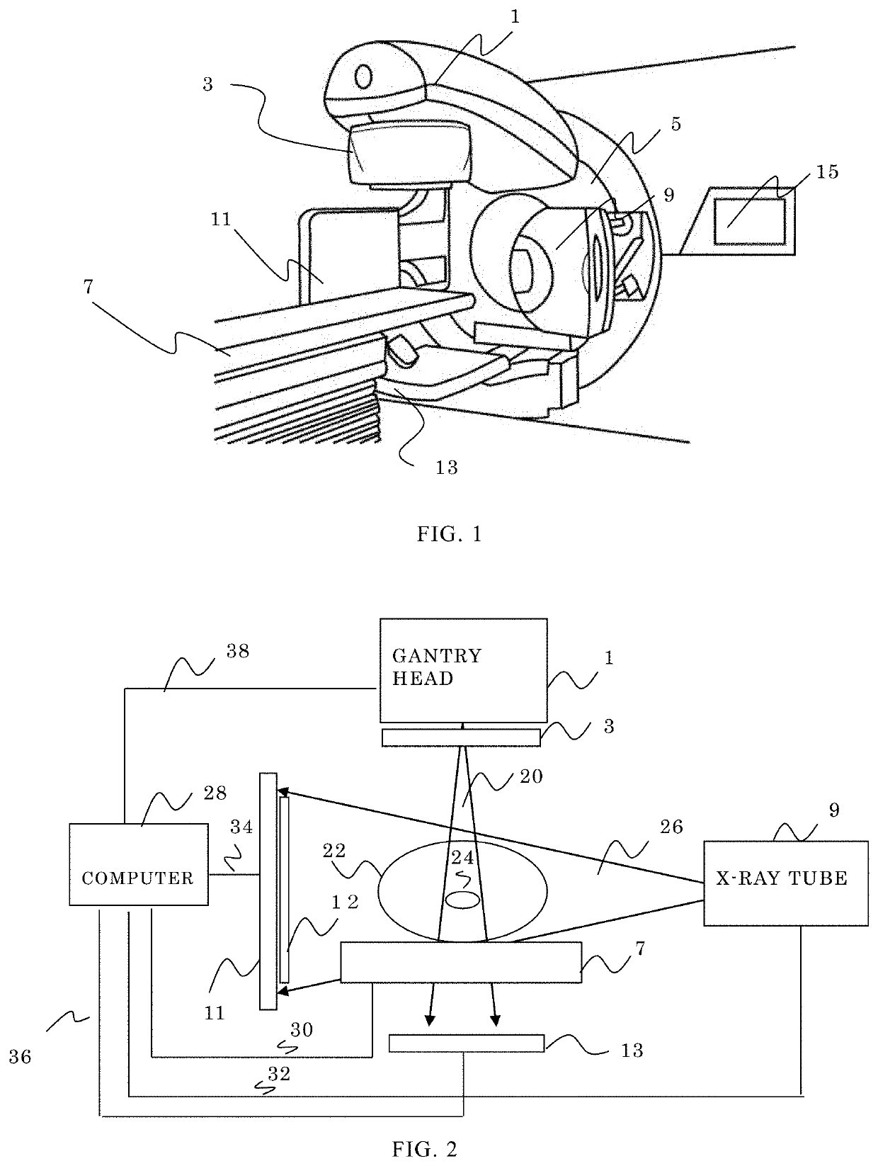
[0068]FIG. 1 shows a perspective view of a radiotherapy machine used for this embodiment, comprising a gantry head 1 that generates treatment beams, a collimator unit 3 that shapes the treatment beam according to a tumor shape, a gantry rotating means 5, a patient couch 7 for positioning the tumor, an x-ray tube 9, a flat panel detector 11 for cone-beam CT imaging, another flat panel detector 13 for treatment beams, and a display 15 that shows the radiotherapy machine status.

[0069]FIG. 2 depicts a block diagram of the radiotherapy machine shown in FIG. 1. A tumor 24 in a patient body 22 is placed at the position of the treatment beams by acquiring the cone-beam CT images of the patient and then moving a high-precision three-axis or six-axis patient couch. An x-ray tube 9 emits cone-shaped x-ray beams 26 towards the patient 22, and then the x-ray beams reach a flat panel detector 11 after passing an anti-scattering grid 12. By rot...

Example

DETAILED DESCRIPTION: SECOND EMBODIMENT WITH FIGS. 14-16

[0095]FIG. 14 is another flowchart that results in improved x-ray cone-beam CT images. In STEP 1, scattering projection images of a predetermined number of patients are calculated from predetermined beam angles.

[0096]In STEP 2, end-to-end training of a multi-layered neural network is performed, based on projection images of the predetermined number of patients as input and the precalculated scattering projection images of the same patients from predetermined beam angles as output. The input and output pair for the training is chosen patient by patient.

[0097]In STEP 3, After the training is completed, scattering projection images for a new patient are estimated by inputting projection images of the new patient into the trained multi-layered neural network.

[0098]In STEP 4, Scatter-free projection images are obtained by subtracting scattering projection images from measured projection images, beam angle by beam angle. A scatter-fr...


PUM


Abstract

An improved x-ray cone-beam CT image reconstruction by end-to-end training of a multi-layered neural network is proposed, which employs cone-beam CT images of many patients as input training data, and precalculated scattering projection images of the same patients as output training data. After the training is completed, scattering projection images for a new patient are estimated by inputting a cone-beam CT image of the new patient into the trained multi-layered neural network. Subsequently, scatter-free projection images for the new patient are obtained by subtracting the estimated scattering projection images from measured projection images, beam angle by beam angle. A scatter-free cone-beam CT image is reconstructed from the scatter-free projection images.

Description

TECHNICAL FIELD[0001]The present invention relates generally to a method for medical x-ray image formation, and more particularly, to an improved method for reconstructing x-ray cone-beam CT images for detecting cancers in a human body, thereby facilitating adaptive radiotherapy planning or other advanced radiotherapy planning techniques that require improved cone-beam CT image quality.BACKGROUND ART[0002]An x-ray cone-beam CT unit is often equipped with a radiotherapy machine for the purpose of tumor positioning inside a patient body. A typical x-ray cone-beam CT unit is described in detail in U.S. Pat. No. 6,842,502, the disclosure of which is hereby incorporated by reference. It is well known that skin marking does not provide accurate tumor positioning and the cone-beam CT facilitates more accurate tumor positioning for treating the tumor.[0003]The x-ray beams emitted from an x-ray tube pass through the patient body and reach a flat panel detector. The flat panel detector detect...

Claims


Application Information

Patent Timeline
IPC IPC(8): A61N5/10G06N3/04G06N3/08
CPCA61N5/1081A61N5/1075A61N2005/1034G06N3/0454G06N3/08A61N5/1031A61N5/1038A61N5/1049A61N2005/1061A61N2005/1076A61B6/032A61B6/4085A61B6/5282A61B6/583G06N3/04G06T11/005G06T2211/441G06T2211/452G06N3/045
Inventor NAKAGAWA, KEIICHI
Owner NAKAGAWA KEIICHI
Why Eureka
Try Eureka