Multi-region light scattering element

Active Publication Date: 2006-03-16
MASSACHUSETTS DEV FINANCE AGENCY
View PDF5 Cites 45 Cited by
  • Summary
  • Abstract
  • Description
  • Claims
  • Application Information

AI Technical Summary

Benefits of technology

[0018] The present invention provides light scattering elements which allow for projection screens and the like having high image contrast, low speckle contrast, high gain, high t

Problems solved by technology

Traditional light scattering elements such as those used in projection screens have progressed over the years with the current designs still suffering from design tradeoffs.
These screens suffered a major drawback due to the loss in contrast due to the backscatter of ambient light.
However, with the industry moving to higher resolution HDTV displays and higher resolution monitors, the requirement for the feature sizes of the reflective or refractive methods such as beaded screens or lenticular screens has become more difficult and more costly.
With lenticular lens pitches now at less than 100 μm, the cost and complexity of manufacturing are becoming larger issues.
However, small arc light sources increase the coherence length and when these are combined with many high resolution projection sources, the resulting image quality suffers from speckle (or scintillation).
It is expected that in the future, the manufacturers will continue to reduce the lamp filament size to increase the optical efficiency and that the projection display resolution will continue to increase, thus speckle will become more of a problem.
A thick single layer reduces the appearance of speckle, but lowers the resolution of the screen.
Two scattering regions spaced apart can reduce the speckle contrast, but also typically decreases the resolution.
This causes a significant decrease in resolution.
This reduces the optical efficiency of the system.
Adding the spherical particles to the Fresnel lens, lenticul

Method used


Image

  • Multi-region light scattering element
  • Multi-region light scattering element
  • Multi-region light scattering element

Examples


Example

EXAMPLE 1

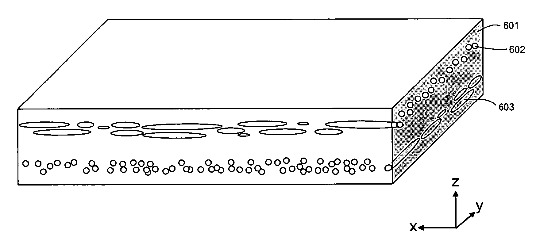
[0125] A multi-region light scattering element, in accordance with the present invention, with asymmetric light scattering features, results in reduced speckle contrast and increased resolution relative to a multiple layer symmetric diffuser. By using two volumetric, asymmetric light scattering regions aligned perpendicular to each other and separated by a substantially non-scattering region, the light is scattered in the x-z plane and then in the y-z plane. The resolution is therefore significantly higher than two symmetric diffusers in both the x-z and y-z plane.

[0126] Sample S1a, a symmetric diffuser with a FWHM of 16 degrees by 16 degrees and gain of 19 was created by dispersing 30% by weight polyethylene particles of refractive index 1.51 within a matrix material of polyester of refractive index 1.568. A multi-layer symmetric scattering element was created by laminating two samples of this symmetric diffuser to either side of a 1.5 mm polycarbonate substrate with a r...

Example

EXAMPLE 2

[0129] Sample S2a, a symmetric diffuser with a FWHM of 29 degrees by 29 degrees and gain of 5.6 was created by dispersing 30% by weight polyethylene particles within a matrix material of polyester. A multi-layer symmetric scattering element was created by laminating two samples of this symmetric diffuser to either side of a 1.5 mm polycarbonate substrate using an index-matched pressure sensitive adhesive. The resulting multiple layer scattering screen (Sample S2b) had a light scattering intensity profile with a FWHM of 42 degrees by 42 degrees with a gain of 2.4. The resolution of this multiple layer scattering screen was measured by illuminating the USAF Test Pattern with collimated light. The screen is in close contact with the pattern such that the horizontal and vertical resolution bars are seen on the screen. On the opposite side of the screen from the diffuser was a CCD camera attached to microscope. Images of the horizontal and vertical line patterns were captured b...

Example

EXAMPLE 3

[0132] A projection screen, in accordance with the present invention, can be produced to have reduced speckle. An asymmetric diffuser with a FWHM of 33 degrees by 6 degrees and gain of 30 was created by dispersing 30% by weight polyethylene particles within a matrix material of polyester and stretching the material as described in U.S. Pat. No. 5,932,342. A multi-region asymmetric scattering element can be created by laminating two samples of this asymmetric diffuser with their major axes of diffusion oriented perpendicular to each other to either side of a 1.5 mm acrylic substrate containing dispersed birefringent mica particles. The resulting diffuser will have an increased resolution and reduced speckle contrast relative to a comparable multilayer symmetric diffuser.


PUM


Abstract

A multi-region light scattering element with the optical characteristics of low speckle, high resolution high contrast, and high gain when used as an imaging element without any resulting loss of transmission or brightness with viewing angle. The multi-region light scattering element contains at least one region asymmetrically shaped light scattering features that are separated from a second light scattering region by a non-scattering region. In one embodiment, one or more of the regions contains particles that are asymmetrically shaped that improve the optical performance. In one embodiment, asymmetric particles are located in two regions separated by a non-scattering region with the particles within each region substantially aligned along an axis and the two axes are substantially perpendicular to each other. Methods for production of the screen element are also described.

Description

RELATED APPLICATIONS [0001] This application claims the benefit of priority under 35 U.S.C. 119(e) to pending U.S. Provisional Application No. 60 / 598,826, filed on Aug. 4, 2004 as Docket No. 28596-001 PRO; the entire contents of which is incorporated herein by reference.FIELD OF THE INVENTION [0002] The invention generally relates to the design of a light scattering element, and methods of manufacture, and more specifically its use in a screen assembly for a rear projection display system, such as those used in televisions, computers, home theatres, information displays and simulation systems. BACKGROUND OF THE INVENTION [0003] Traditional light scattering elements such as those used in projection screens have progressed over the years with the current designs still suffering from design tradeoffs. Some of the key merits for describing a projection screen include, gain, angle of view, resolution, transmission, screen contrast, speckle contrast, and cost. The ideal projection screen ...

Claims


Application Information

Patent Timeline
IPC IPC(8): G03B21/56
CPCG02B5/0242G02B5/0278G03B21/625G03B21/62G03B21/10
Inventor YEO, TERENCE E.COLEMAN, ZANE A.
Owner MASSACHUSETTS DEV FINANCE AGENCY
Why Eureka
Try Eureka