
Phase shift mask

Inactive Publication Date: 2006-03-07
INTELLECTUAL DISCOVERY CO LTD
View PDF1 Cites 0 Cited by
  • Summary
  • Abstract
  • Description
  • Claims
  • Application Information

AI Technical Summary

Benefits of technology

[0016]It is an object of the present invention to provide a phase shift mask comprising a quartz substrate region, a phase shift region of 100% transparency and a half-tone phase shift region for high image contrast and improved resolution.

Problems solved by technology

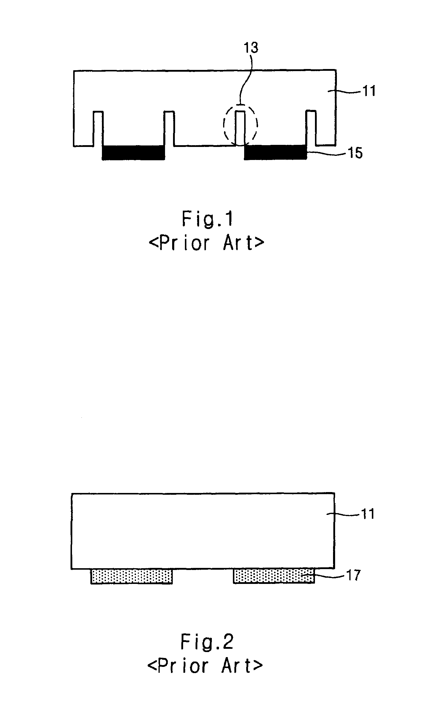
However, since the amount of a transmitted light is large, diffractions and interferences occur in a high density pattern region and desired patterns are formed while it is difficult to form a pattern in a low density pattern region due to direct transmission of the light.

Method used


Image

  • Phase shift mask
  • Phase shift mask
  • Phase shift mask

Examples


Embodiment Construction

[0026]The present invention will be described in detail referring to the accompanying drawings.

[0027]FIG. 4 is a diagram illustrating a phase shift mask and the amplitude of light at the mask according to a preferred embodiment of the present invention.

[0028]Referring to FIG. 4, a phase shift mask according to a preferred embodiment of the present invention comprises a quartz substrate 31 having a trench-type guard ring pattern 33 for shifting the phase of transmitted light by 180°, a half-tone phase shift pattern 35 disposed on the quartz substrate 31 to be surrounded by the guard ring pattern 33.

[0029]The quartz substrate 31 and the guard ring pattern 33 have transparency of 100%, respectively. Preferably, the transparency of the half-tone phase shift pattern ranges from 0 to 25%, and the half-tone phase shift pattern shifts the phase of transmitted light by 0° or 180°.

[0030]A ratio of the area of the guard ring pattern 33 and the half-tone phase shift pattern 35 or the shape of t...


PUM


Abstract

A phase shift mask, comprising a transparent substrate having a trench-type guard ring pattern for shifting the phase of light transmitted therethrough by 180°; and a half-tone phase shift pattern disposed on the transparent substrate and surrounded by the guard ring pattern is disclosed.

Description

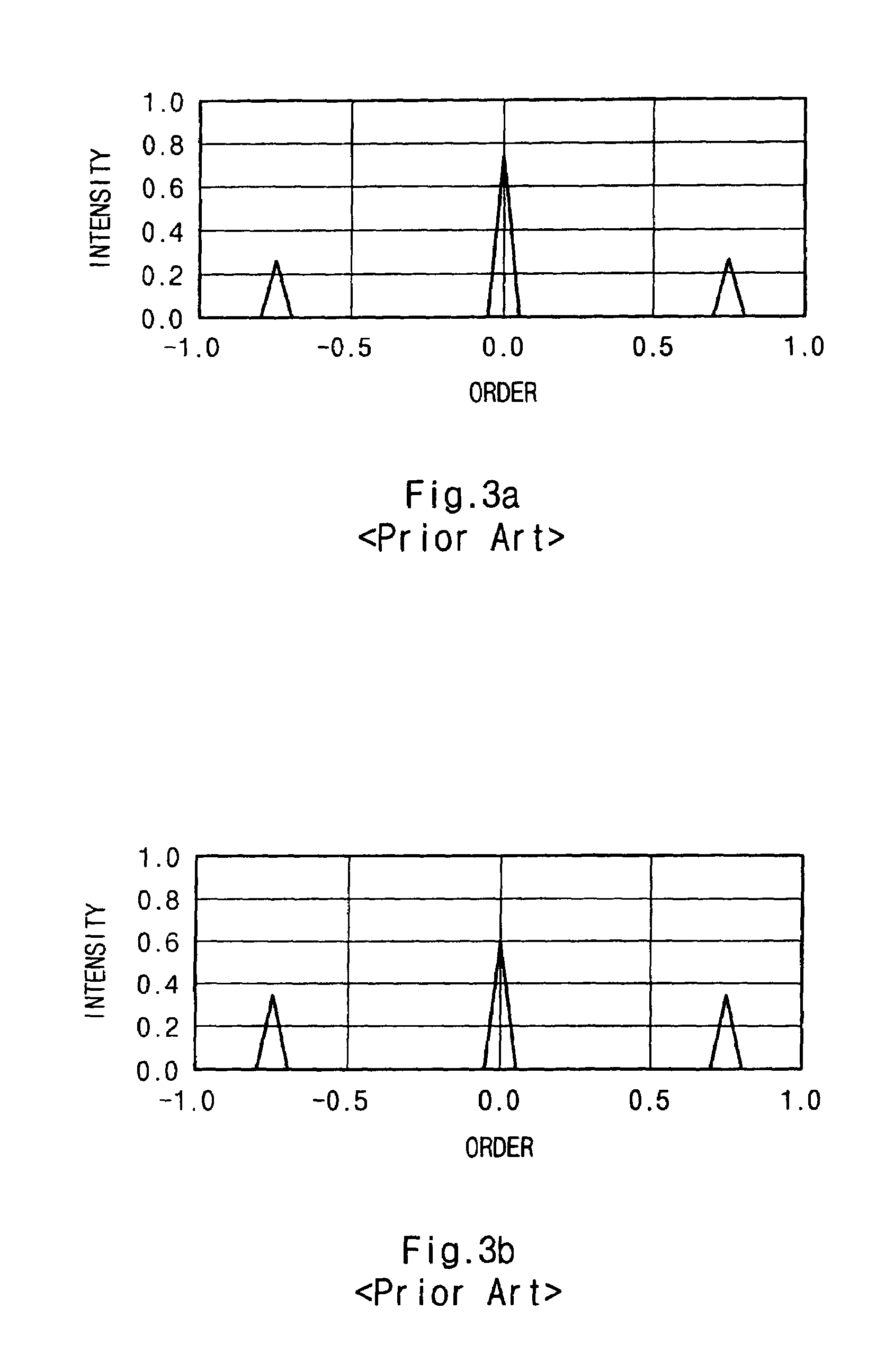
BACKGROUND OF THE INVENTION[0001]1. Field of the Invention[0002]The present invention generally relates to a phase shift mask, and more specifically to a tri-tone phase shift mask comprising a quartz substrate region, a phase shift region having a transparency of 100% and a half-tone phase shift region.[0003]2. Description of the Prior Art[0004]Various types of phase shift masks are used to improve the limit in resolution in a lithography process of fabricating process of semiconductor devices.[0005]In the lithography process, an image is obtained by interference of a light of zero order and a light of first order. A diffracted light is a plane wave which does not contain any information on a mask. A pattern on the mask is transferred to a wafer by interference of two diffracted lights.[0006]Here, an image contrast is a ratio of intensities of the light of zero order to that of the light of first order. When the intensities of two diffracted lights are analogous, complete interferen...

Claims


Application Information

Patent Timeline
IPC IPC(8): G03F9/00H01L21/027G03F1/29G03F1/32
CPCG03F1/32G03F1/29H01L21/027
Inventor LIM, CHANG MOONKIM, SEO MIN
Owner INTELLECTUAL DISCOVERY CO LTD
Learn More