Vaporizer apparatus having both a vacuum pump and a heating element, and method of using same

a vacuum pump and vaporizer technology, applied in the field of hand-held vaporizer devices, can solve the problems of inhaling vapor, disadvantages of existing vaporizer devices, chemical changes, etc., and achieve the effects of reducing the pressure inside the chamber, and reducing the temperature of vaporization

Active Publication Date: 2021-02-25
MABEE ENGINEERED SOLUTIONS INC
View PDF9 Cites 4 Cited by
  • Summary
  • Abstract
  • Description
  • Claims
  • Application Information

AI Technical Summary

Benefits of technology

[0009]The present invention combines the properties of vacuum evaporation to a vaporizing apparatus used to generate an inhalable vapor, where a vacuum pump is used in conjunction with a heater in the apparatus. By creating a temporarily sealed chamber inside of the apparatus which contains a quantity of oil to be vaporized, and by both heating the chamber and lowering the pressure inside of the chamber, the apparatus is operable to vaporize the oil at reduced temperatures, thereby reducing the temperature of vaporization below what would be required using a heater alone.
[0010]It is believed that by reducing the operating temperature attained in the vaporizing apparatus, the vaporized oil which is generated by the apparatus will be less toxic, and less hazardous to the health of a user, than the vaporized oil which is generated by conventional “vaping” apparatus which exclusively uses a heater at atmospheric pressure.
[0011]The present invention, according to one aspect thereof, provides a vaporizer apparatus that can produce vapors from a selected liquid substance at a temperature which is elevated above normal room temperature and at a reduced pressure.

Problems solved by technology

The existing vaporizer apparatus are disadvantageous because they exclusively use a heating element (e.g., a heating coil) for heating, and vaporizing the oil.
In some instances, chemical changes may take place due to overheating the oil.
In addition, there is a risk of inhaling vapor near a combustion temperature, which may injure a person's throat, due to inhalation of a harsh and / or hot vapor.

Method used


Image

  • Vaporizer apparatus having both a vacuum pump and a heating element, and method of using same
  • Vaporizer apparatus having both a vacuum pump and a heating element, and method of using same
  • Vaporizer apparatus having both a vacuum pump and a heating element, and method of using same

Examples


first embodiment

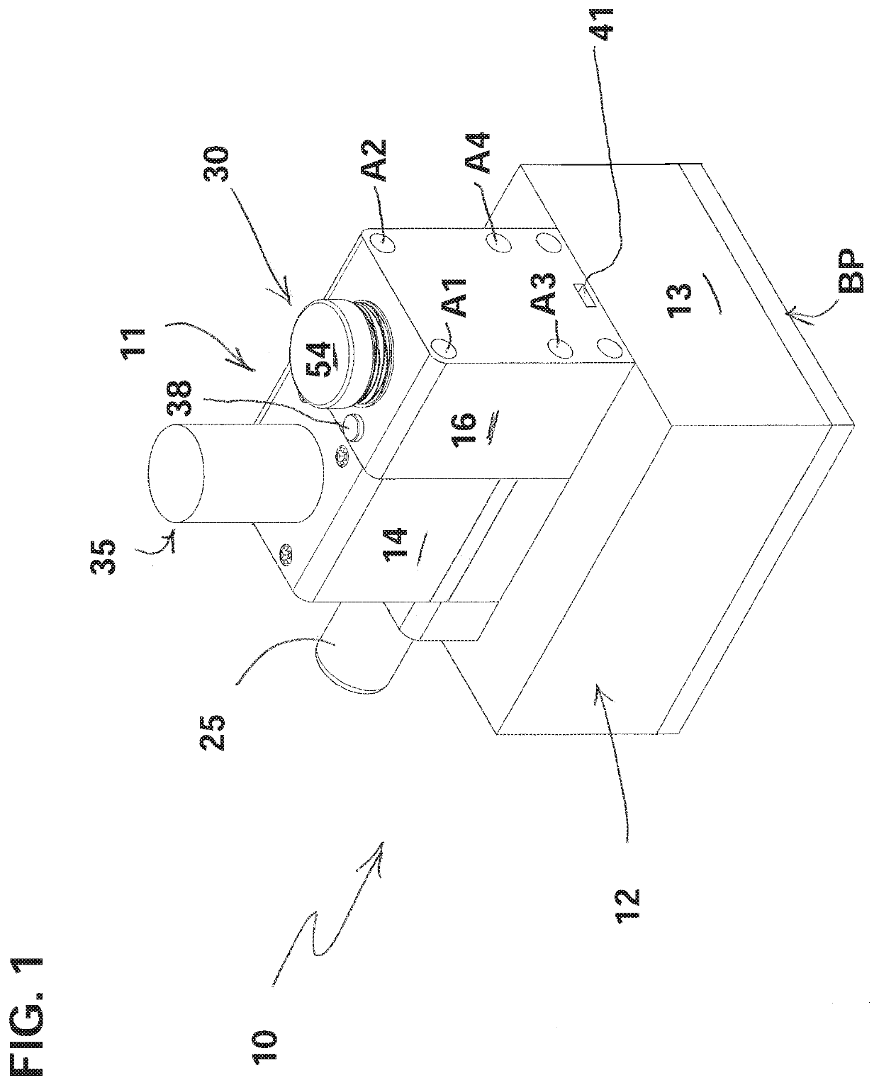
[0060]A vaporizer apparatus 10 according to a first embodiment of the present invention is shown in FIGS. 1-7. FIG. 1 is a perspective view of the vaporizer apparatus 10 according to the first embodiment of the present invention, as viewed from an upper right rear vantage point.

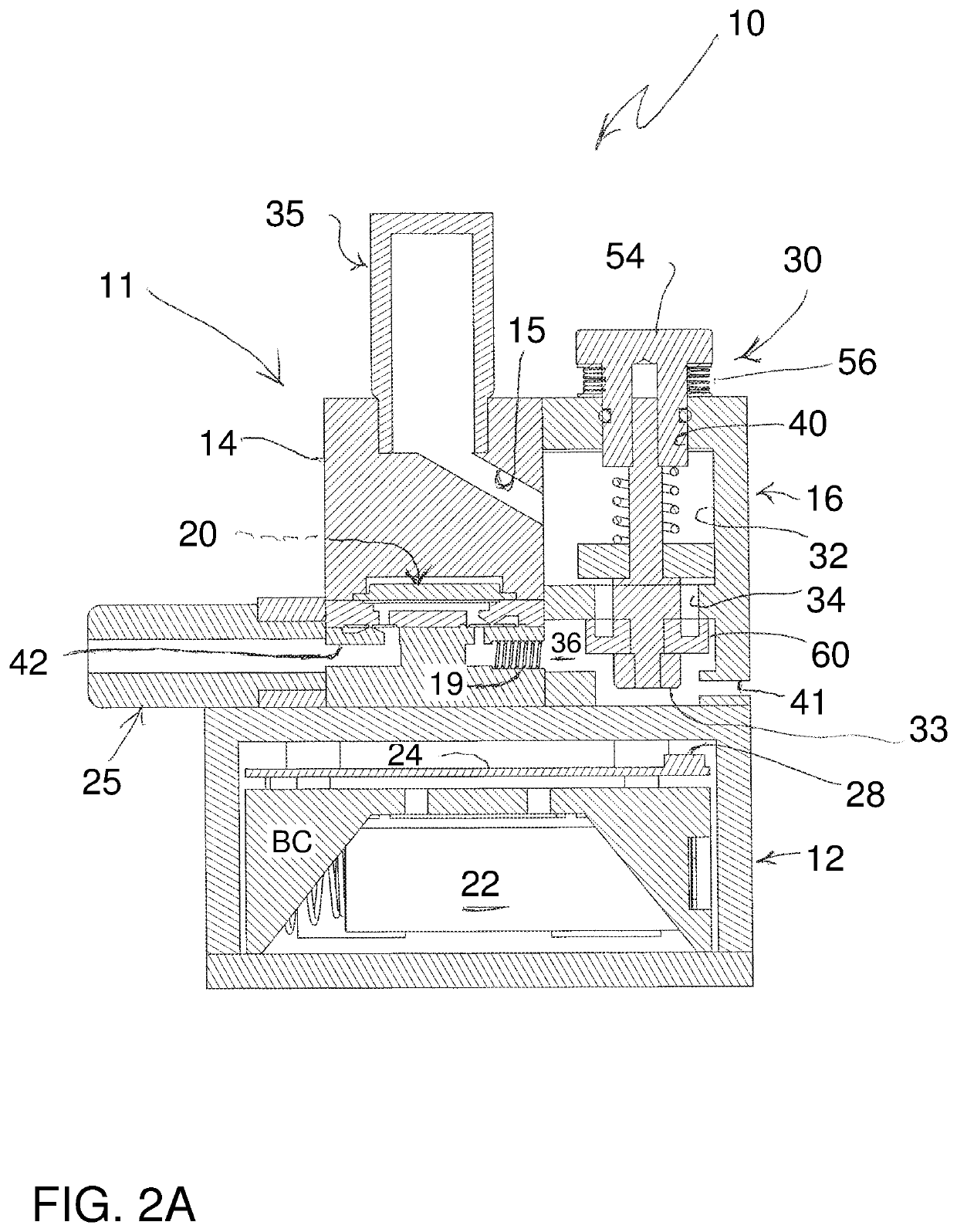
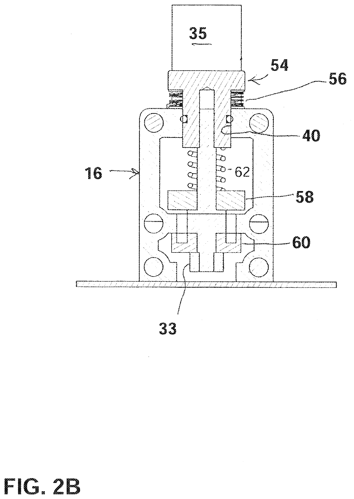
[0061]FIG. 2A is a first cross-sectional view of the vaporizer apparatus of FIG. 1, taken along a central longitudinal vertical plane. FIG. 2B is a second cross-sectional view of the vaporizer apparatus of FIG. 1, taken along a lateral vertical plane which extends through a central portion of the chamber housing.

[0062]FIG. 3 is an exploded perspective view of the vaporizer apparatus of FIG. 1, as viewed from an upper right rear vantage point.

[0063]As shown in FIGS. 1-3, the vaporizer apparatus 10 generally includes a main housing 11, a control housing 12 connected to and disposed below the main housing 11, and an operation unit 30 mounted in a hollow bore 40 in the main housing 11. The vaporizer apparatus 10 ...

second embodiment

[0114]A vaporizer apparatus 101 according to a second embodiment of the present invention is shown in FIGS. 10A-10B and 11-14. FIG. 10A is a perspective view of a vaporizer apparatus 101 as viewed from a right rear top vantage point according to the second embodiment of the present invention, and FIG. 10B is a perspective view of the vaporizer apparatus 101 of FIG. 10A as viewed from a lower right vantage point. The vaporizer apparatus 101 of the second embodiment is similar to the vaporizer apparatus 10 according to the first embodiment as previously described, and shares many of the same modular components. Components of the vaporizer apparatus 101 according to the second embodiment, which are shared with the vaporizer apparatus 10 of the first embodiment, are given the same numbers in the drawings.

[0115]The apparatus 101 according to the second embodiment also includes a heating element 19 (FIG. 14) in the evacuation chamber, in a manner similar to that described in connection wi...

third embodiment

[0119]A vaporizer apparatus 110 according to a third embodiment of the present invention is shown in FIGS. 15-21. FIG. 15 is a perspective view of the vaporizer apparatus 110 as viewed from right front top according to the third embodiment of the present invention.

[0120]As shown in FIG. 15, the vaporizer apparatus 110 generally includes a control housing (also referred to as a battery / circuit board housing) 120, a main housing 130 connected to the control housing 120, an operation unit 150 mounted into the main housing 130, a manifold 170 (also referred to as an air flow chamber) connected to the main housing 130, a pump 180 connected to the manifold 170, and a mouthpiece 190 connected to the manifold 170.

[0121]The apparatus 110 according to the third embodiment also includes a heating element 19 (FIGS. 16, 19) in the evacuation chamber, in a manner similar to that described in connection with the first embodiment.

[0122]The pump 180 used in the present invention may be a piezo elect...


PUM


Abstract

A vaporizer apparatus includes a pump housing, a main housing containing an evacuation chamber, and an operation unit attached to the main housing. The operation unit selectively isolates the evacuation chamber from communication with an air inlet. At least one vacuum pump is operable to generate a vacuum in the evacuation chamber, while a heating element also operates. A mouthpiece is attached to the main housing, and may be selectively placed in communication with the evacuation chamber. When oil is placed in the evacuation chamber and the operation unit is operated, the evacuation chamber is temporarily sealed off from the inlet, creating a vacuum sealed chamber connected with the pump(s). Then, the pump(s) is / are activated to reduce pressure in the evacuation chamber, and the oil is vaporized at reduced pressure and at an elevated temperature. When the operation unit is released, the evacuation chamber is emptied via the mouthpiece.

Description

CROSS-REFERENCE TO RELATED APPLICATIONS[0001]This application is a continuation-in-part of, and claims the benefit of priority from U.S. application Ser. No. 16 / 683,765, filed on Nov. 14, 2019, which is a continuation-in-part of, and claims the benefit of priority from U.S. application Ser. No. 16 / 549,241, filed on Aug. 23, 2019. The entire disclosure of each of these referenced priority documents, including specification, claims and drawings, is incorporated by reference herein.BACKGROUND OF THE INVENTION1. Field of the Invention[0002]The present invention relates to a handheld vaporizer apparatus for vaporizing liquids, such as e-liquids, Cannabis oil or other vaporizable and inhalable liquids, either at or below room temperature. More particularly, the present invention relates to a handheld vaporizer apparatus that is operable to vaporize oil or other materials at or below room temperature using a heating element, and simultaneously reducing the pressure in a chamber containing ...

Claims


Application Information

Patent Timeline
Patent Type & Authority Applications(United States)
IPC IPC(8): A24F40/51A24F7/00A24F40/485
CPCA24F40/51A24F40/485A24F7/00A24F40/10A24F40/48
Inventor MABEE, BRIAN D.MABEE, KATHRYNMABEE, AUSTIN M.LONGFELLOW, MARC
Owner MABEE ENGINEERED SOLUTIONS INC
Why Eureka
Try Eureka