
Modular power conversion system with galvanic insulation

a technology of transformer components and galvanic insulation, which is applied in the direction of power conversion systems, ac-ac conversion, electrical apparatus, etc., can solve the problems of large and complex insulation between transformer components such as primary and secondary windings and cores, which cannot meet adequate functional and safety isolation requirements, and dry-type transformers using insulating materials such as epoxy are susceptible to partial discharge breakdown, etc., to reduce electromagnetic interference and reduce the enclosed loop area

Active Publication Date: 2021-03-04
RAJU RAVISEKHAR NADIMPALLI
View PDF0 Cites 2 Cited by
  • Summary
  • Abstract
  • Description
  • Claims
  • Application Information

AI Technical Summary

Benefits of technology

This patent describes a system where modular building blocks with transformers and power converter bridges are connected through a high-frequency current link. This link is insulated from the building blocks using a strong tube, which increases the structure's strength and prevents electrical arcing. The insulating tube can be extended over multiple building blocks to enhance its integrity. The system also includes multiple transformers within the building blocks to minimize interference between them. Overall, this technology increases the reliability and performance of power conversion systems.

Problems solved by technology

However, for higher voltage applications, even though the transformer core and windings can be reduced through the use of higher frequency, the insulation used between transformer components such as primary and secondary windings and core often remains sizeable and complex to satisfy adequate functional and safety isolation requirements.
In many applications, oil-filled transformers are not preferred due to issues such as flammability or possibility of leaks.
Dry-type transformers using insulating materials such as epoxy are susceptible to partial discharge breakdown particularly if there are voids or pockets of air in the dielectric space.
They are also generally more difficult to manufacture and costlier than oil-filled transformers for high power applications.

Method used


Image

  • Modular power conversion system with galvanic insulation
  • Modular power conversion system with galvanic insulation
  • Modular power conversion system with galvanic insulation

Examples


Embodiment Construction

[0020]Various embodiments and aspects of the inventions will be described with reference to details discussed below, and the accompanying drawings will illustrate the various embodiments. The following description and drawings are illustrative of the invention and are not to be construed as limiting the invention. Numerous specific details are described to provide a thorough understanding of various embodiments of the present invention. However, in certain instances, well-known or conventional details are not described in order to provide a concise discussion of embodiments of the present inventions.

[0021]Reference in the specification to “one embodiment” or “an embodiment” or “another embodiment” means that a particular feature, structure, or characteristic described in conjunction with the embodiment can be included in at least one embodiment of the invention.

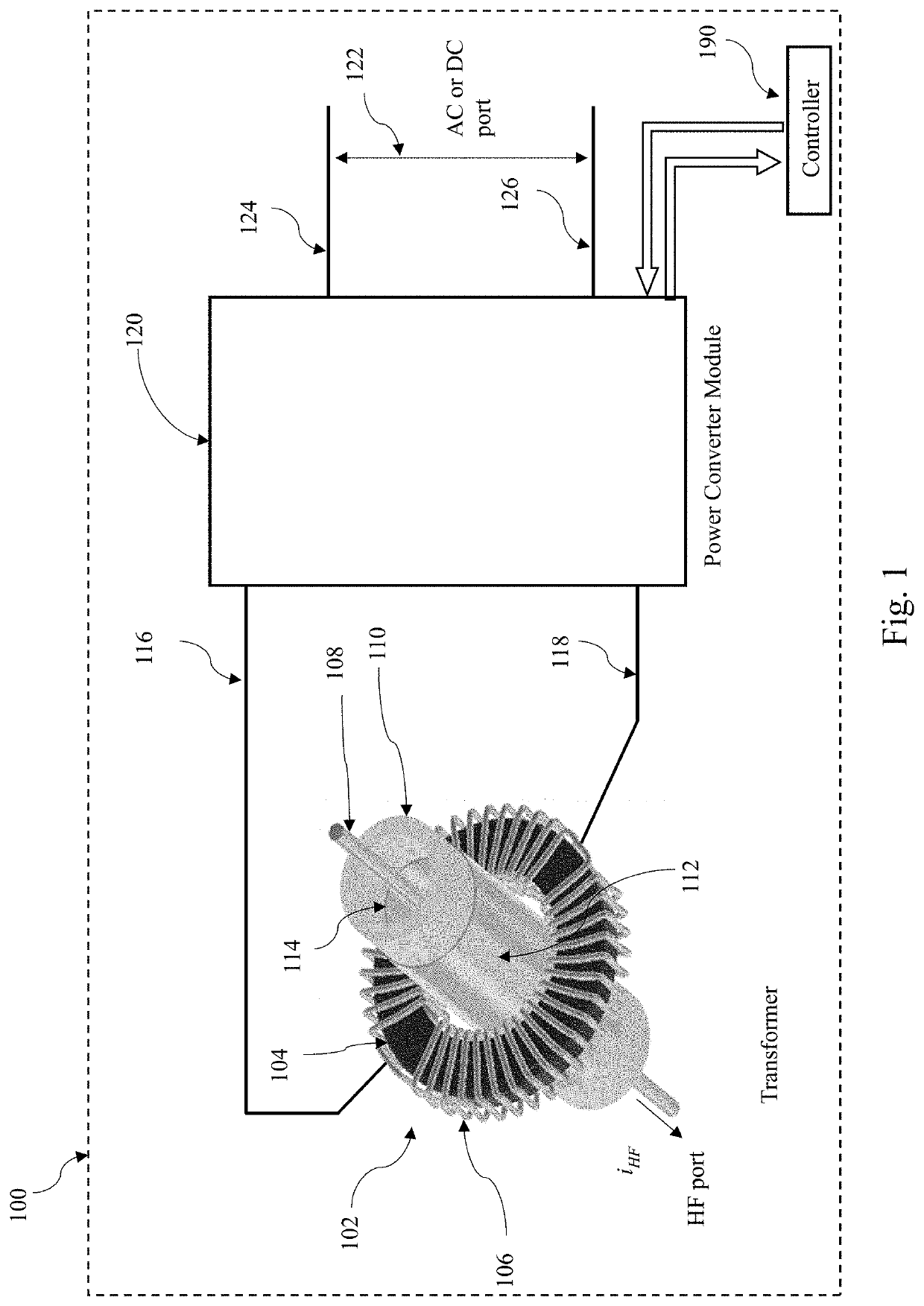
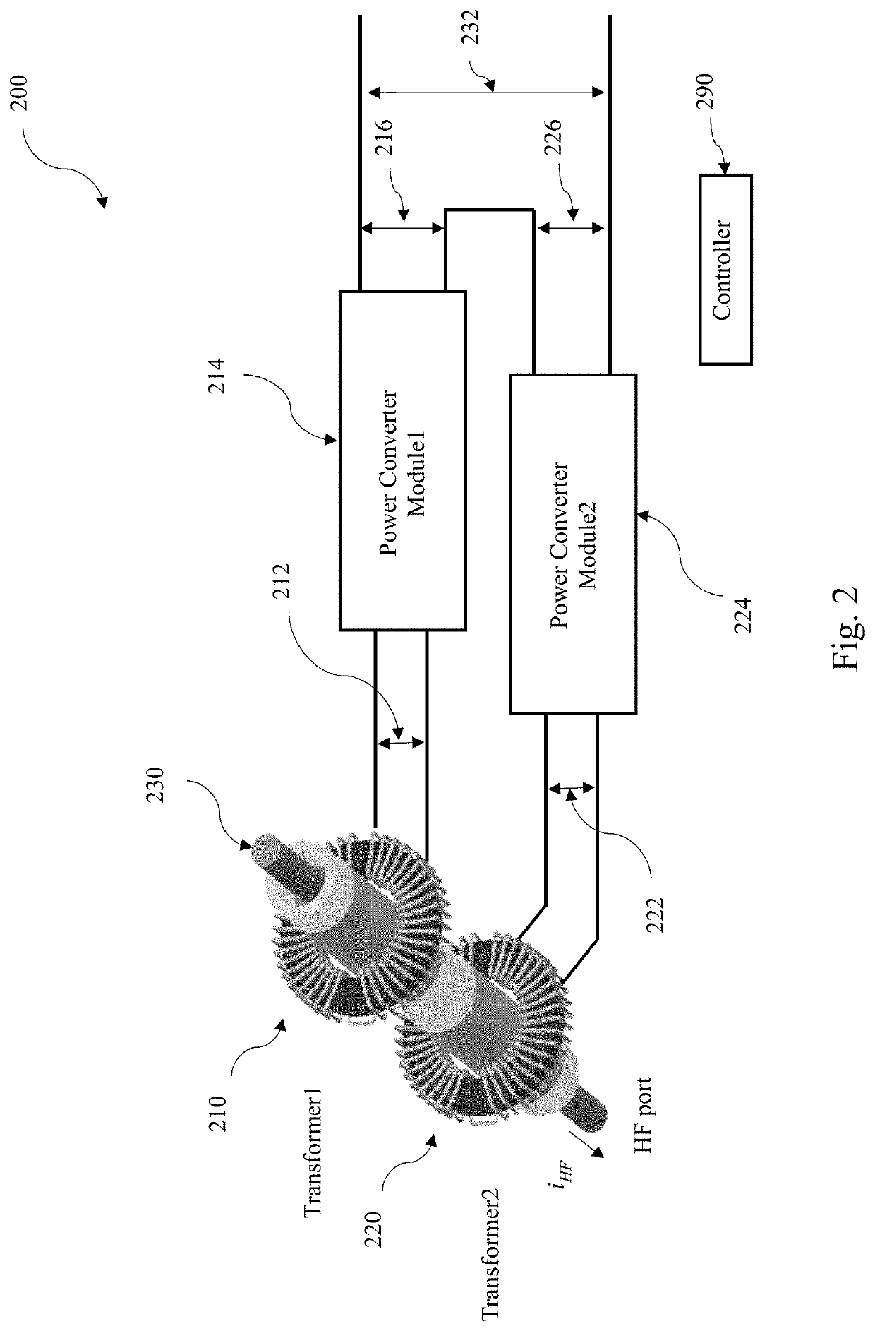
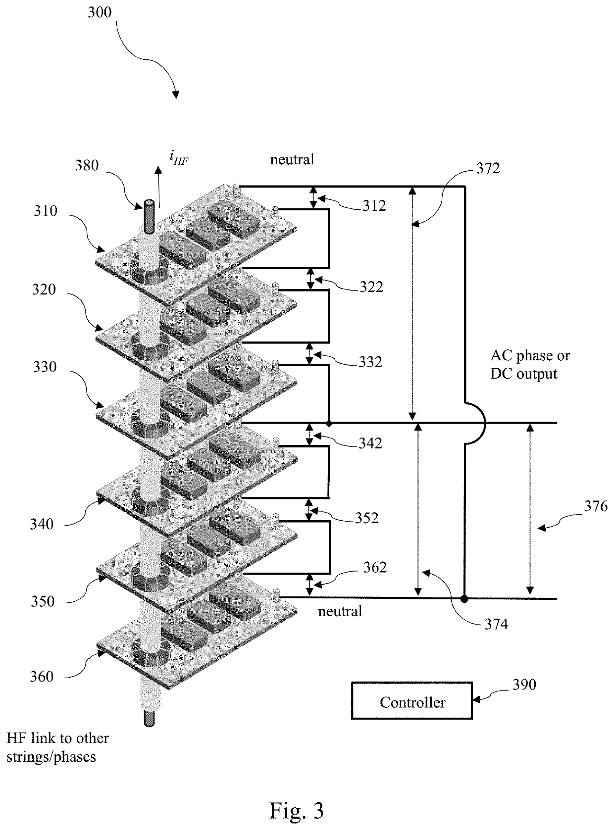
[0022]FIG. 1 illustrates a building block, 100, for a power conversion system with modular transformer and power converter ...


PUM


Abstract

A modular power conversion system is provided which includes a plurality of building blocks comprised of transformers and power conversion bridges, and a high frequency AC link that transfers power and provides galvanic isolation between the building blocks. The high frequency link includes an insulating tube separating an AC link conductor and the building blocks. The insulating tube is further provided with conductive or semiconductive layers on its inner and outer surfaces for referencing them to the electric potentials of the adjacent conductors and windings, thereby placing the high electric fields substantially directly across the tube and reducing electric fields and partial discharge or corona in the adjoining space or media. The building blocks may be arranged in multiple stacks for DC or AC interface, preferably with neutral or lower voltage connections at the outer edges of the stacks and higher voltage terminals at the centers of the stack.

Description

CROSS-REFERENCE TO RELATED APPLICATION[0001]This application claims the benefit of U.S. Provisional Patent Application No. 62 / 891,946, filed 26 Aug. 2019, which is incorporated by reference herein in its entirety.STATEMENT OF GOVERNMENT INTEREST[0002]Portions of this invention were made with government support under DE-SC0020859 awarded by Office of Science, U.S. Department of Energy. The government has certain rights in the invention.BACKGROUND[0003]The present disclosure relates to a modular power conversion system with galvanic insulation. Specifically, the present invention relates to a modular power conversion system with building blocks comprising transformers and power converter bridges wherein the building blocks are coupled through a high frequency AC link.[0004]Transformers are widely used in electric power systems for functions such as step-up or step-down of voltages. They are often used in concert with switching power devices such as power semiconductors to provide powe...

Claims


Application Information

Patent Timeline
Patent Type & Authority Applications(United States)
IPC IPC(8): H02M5/293H02M7/217H02M5/10
CPCH02M5/293H02M5/10H02M7/2173H02M7/49H02M5/225H02M7/4807H02M1/0077H02M1/0067H02M1/0074H02M1/0083
Inventor RAJU, RAVISEKHAR NADIMPALLI
Owner RAJU RAVISEKHAR NADIMPALLI
Learn More