Image processing device, image processing method and storage medium

Active Publication Date: 2021-03-25
NEC CORP
View PDF0 Cites 0 Cited by
  • Summary
  • Abstract
  • Description
  • Claims
  • Application Information

AI Technical Summary

Benefits of technology

The invention aims to minimize the computer resources required to estimate the positions of particles in an image.

Problems solved by technology

The observation of positions of overlapping particles within a distance less than the wavelength of the light source is difficult because of the Abbe diffraction limit.

Method used


Image

  • Image processing device, image processing method and storage medium
  • Image processing device, image processing method and storage medium
  • Image processing device, image processing method and storage medium

Examples


first example embodiment

[0022]A first example embodiment of the present invention will be explained in detail with reference to drawings.

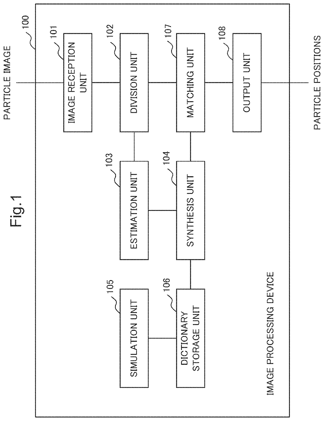
[0023]FIG. 1 is a block diagram showing an example configuration of an image processing device 100 according to the first example embodiment of the present invention.

[0024]The image processing device 100 includes an image reception unit 101, a division unit 102, an estimation unit 103, a synthesis unit 104, a simulation unit 105, a dictionary storage unit 106, a matching unit 107 and an output unit 108.

[0025]The image reception unit 101 receives a particle image, e.g. an observed microscopic image of particles. A particle of the particle image overlaps with another particle. More specifically, an area of a particle in the particle image may overlap with an area of another particle in the particle image. A distance between particles may be less than a half of a wavelength of a light emitted by a light source. In such cases, a distance between the particles may not be deter...

second example embodiment

[0094]A second example embodiment of the present invention will be explained in detail with reference to drawings.

[0095]FIG. 1 is a block diagram showing an example of a configuration of an image processing device 100 according to the second example embodiment of the present invention. The configuration of the image processing device 100 of the present example embodiment is the same as that of the image processing device 100 of the first example embodiment except the following differences. Elements of the present example embodiment operate in the same way as the elements to which the same names and signs are assigned of the first example embodiment except the following different operations.

[0096]In summary, the simulation unit 105 and the synthesis unit 104 use powers of two instead of the Fibonacci numbers. The predetermined set of numbers described above is a set of powers of two in the present example embodiment. The simulation unit 105 of the present example embodiment is the sa...

third example embodiment

[0118]The third example embodiment of the present disclosure is described in detail with reference to drawings.

[0119]FIG. 6 is a block diagram representing an example configuration of an image processing device according to the present example embodiment.

[0120]The image processing device 200 of the present example embodiment includes a division unit 102, an estimation unit 103, a synthesis unit 104, a matching unit 107 and an output unit 108.

[0121]The division unit 102 extracts a cluster image including a cluster of particles from a particle image. The particle image may be a microscopic image of particles.

[0122]The estimation unit 103 estimates particle density (i.e. density of particles) of the cluster image.

[0123]The synthesis unit 104 determines numbers on the basis of the estimated particle density. In other words, the synthesis unit 104 determines numbers equal to an integer based on the estimated particle density. More specifically, the synthesis unit 104 may determine Fibona...


PUM


Abstract

An image processing device according to an aspect of the present invention includes: at least one memory storing a set of instructions; and at least one processor configured to execute the set of instructions to: extract a cluster image including a cluster of particles from a particle image; estimate particle density of the cluster image; determine numbers based on the particle density, and synthesize a second dictionary image from first dictionary images having densities each being equal to the numbers, the first dictionary images being images of particles of which positions is obtained; match the second dictionary image with the partial image, and determine positions of particles in the cluster image based on a result of the matching and the positions of particles of the first dictionary images; and output the determined positions of particles.

Description

TECHNICAL FIELD[0001]The present invention is related to an image processing technology.BACKGROUND ART[0002]In microscopic particle position estimation by using an exemplar based method, the positions of overlapping particles on microscopic images are estimated. The observation of positions of overlapping particles within a distance less than the wavelength of the light source is difficult because of the Abbe diffraction limit. The exemplar based method is one of the ways to solve this optical problem.[0003]In the exemplar based method, a dictionary (i.e. database) which contains microscopic particle images and their known particle positions is included in the system, in order to provide information for particle position estimation on input microscopic images.[0004]When a microscopic image is input into the system, the image may be divided into images of clusters of overlapping particles. Each of the clusters is matched with the images in the dictionary. The positions of the particl...

Claims


Application Information

Patent Timeline
IPC IPC(8): G06T7/73G06K9/62G06K9/00
CPCG06T7/74G06K9/6255G06T2207/20021G06K9/0014G06T2207/10056G06K9/6202G06V20/698G06V20/695G06F18/28
Inventor LEE, KAPIKSHIBATA, TAKASHISATO, ATSUSHI
Owner NEC CORP
Why Eureka
Try Eureka