

Reinforcement structure and process for reinforcement of a panel element
- Summary
- Abstract
- Description
- Claims
- Application Information
AI Technical Summary
Benefits of technology
Problems solved by technology
Method used
Image

Examples
Embodiment Construction
Brief Description of the Figures
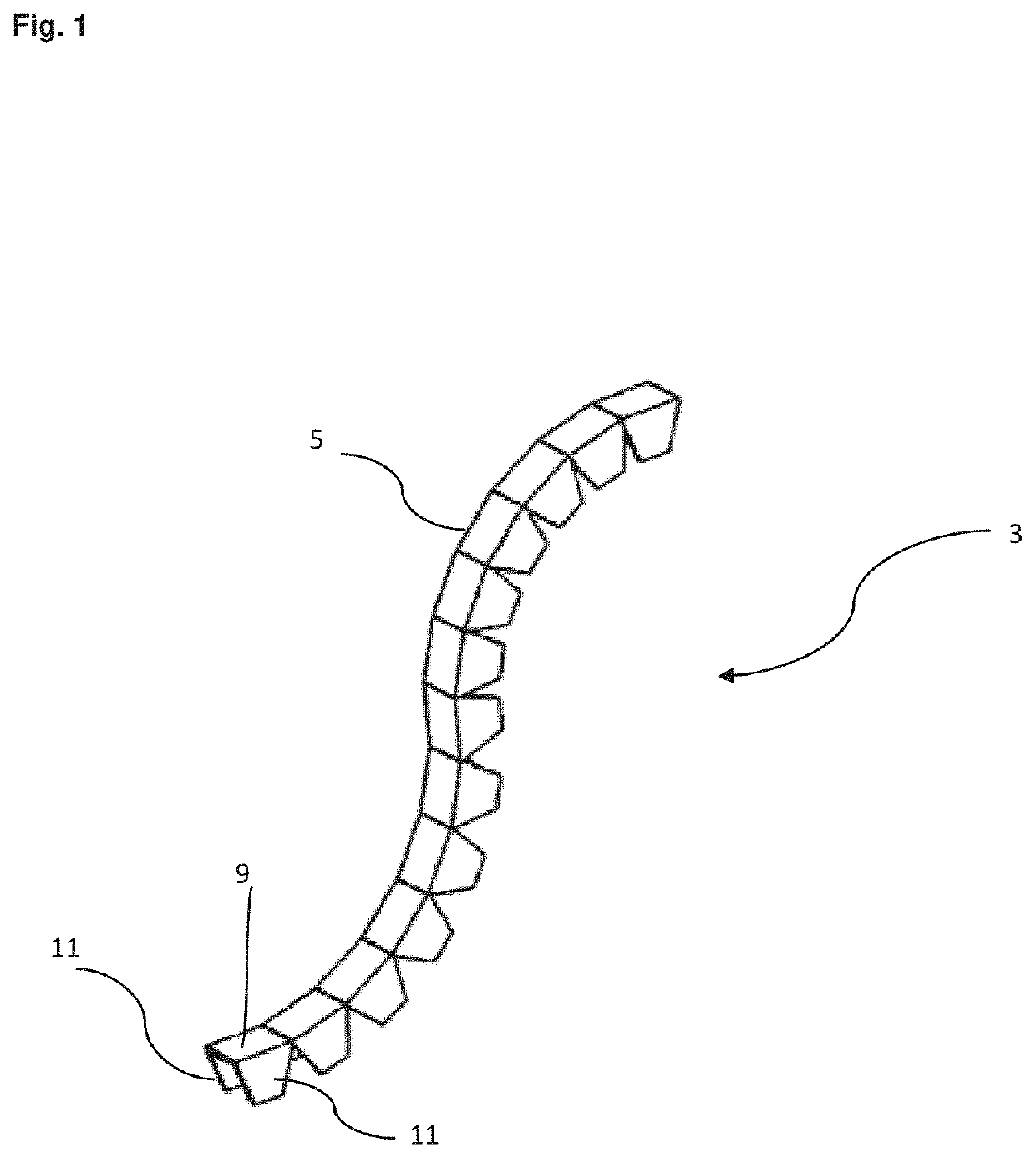
[0139]FIG. 1 Illustration of a preferred stiffening structure
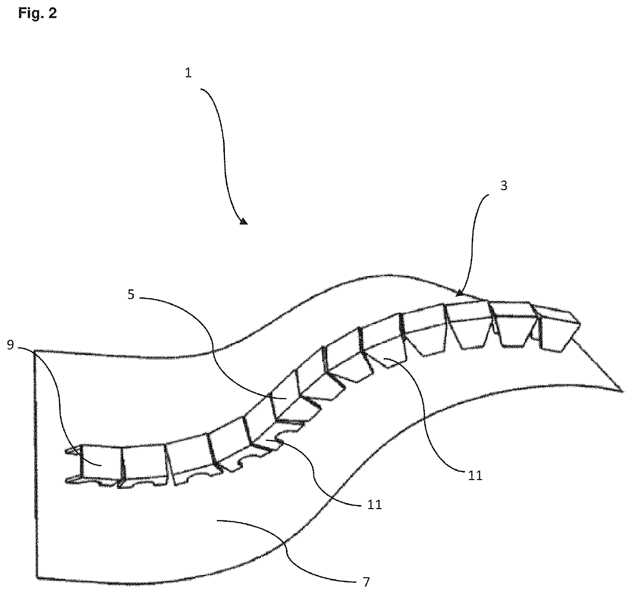
[0140]FIG. 2 Illustration of a preferred stiffening system
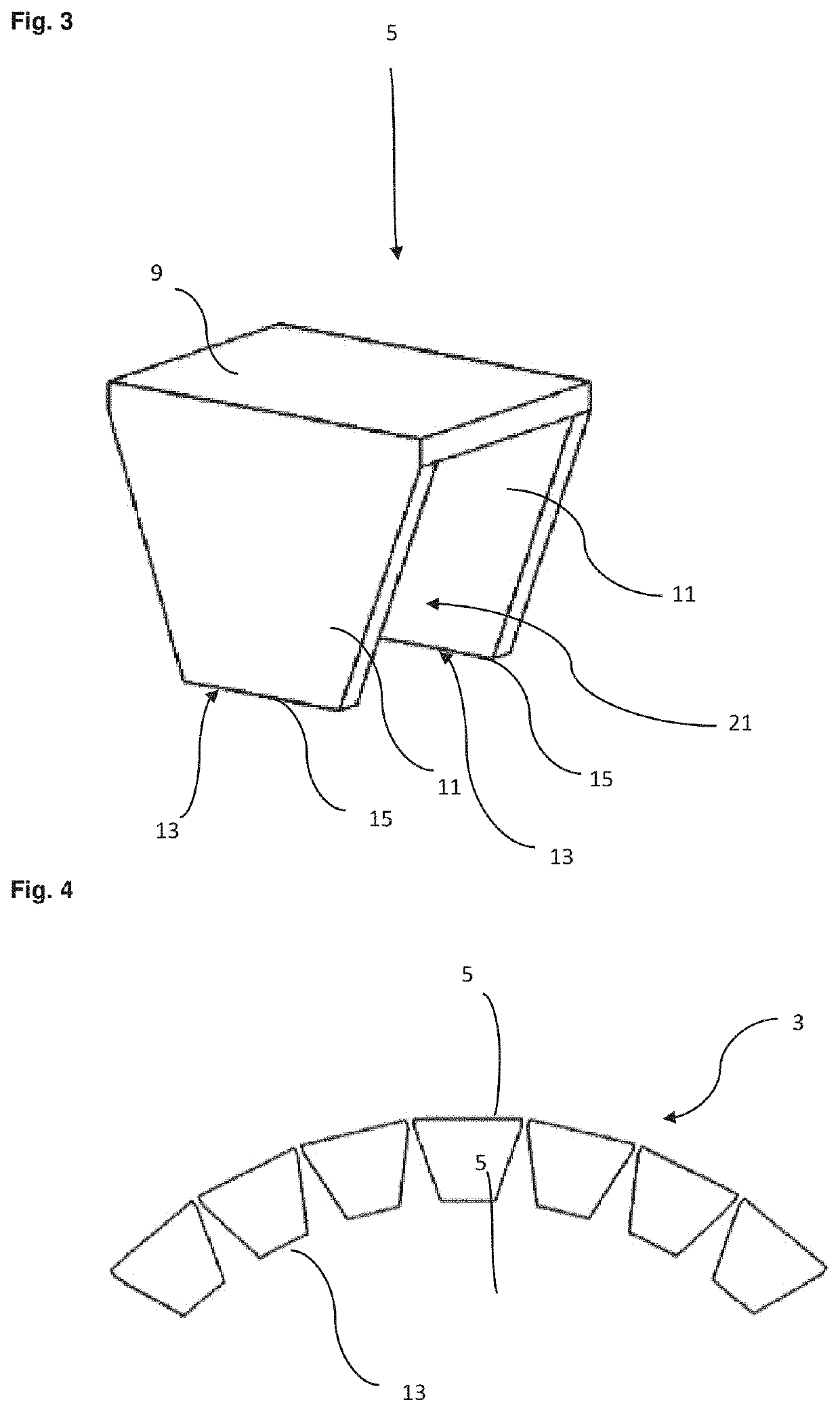
[0141]FIG. 3 Illustration of a preferred stiffening module
[0142]FIG. 4 Illustration of a preferred stiffening structure comprising seven stiffening modules
[0143]FIG. 5 Illustration of a preferred stiffening system
[0144]FIG. 6 Schematic representation of preferred stiffeners from the prior art
[0145]FIG. 7 Comparison of preferred stiffening systems according to the invention and a stiffening system from the prior art
[0146]FIG. 8 Comparison of conventional manufacturing processes for the production of stiffening structures with a preferred process
[0147]FIG. 9A Preferred stiffening system on a concave sheet element
[0148]FIG. 9B Preferred stiffening system on a convex sheet element
[0149]FIG. 10A Preferred stiffening module with two webs
[0150]FIG. 10B Preferred stiffening structure formed by the stiffening modules of FIG. 10A
[0151]FIG. 11 P...
PUM
| Property | Measurement | Unit |
|---|---|---|
| Length | aaaaa | aaaaa |
| Fraction | aaaaa | aaaaa |
| Fraction | aaaaa | aaaaa |
Abstract
Description
Claims
Application Information