
System and method for producing hollow fibre membranes

Pending Publication Date: 2022-03-24
FRESENIUS MEDICAL CARE DEUTSCHLAND GMBH
View PDF0 Cites 0 Cited by
  • Summary
  • Abstract
  • Description
  • Claims
  • Application Information

AI Technical Summary

Benefits of technology

The invention is about a method to produce hollow fiber membranes with porous walls that are filled with liquid when produced. By using a drying process with positive pressure, the inventors found that they can separate most of the liquid from the membrane, reducing its weight and allowing for faster transport without damage. This also allows for lower temperatures and shorter drying times, saving energy and reducing damage to the membrane. Additionally, the membranes produced using this method have a low residual content of solvent, which further improves their quality.

Problems solved by technology

Depending on the transport speed, this results in a predetermined residence time of the hollow fiber membranes in the drying chamber.
However, the transport speed cannot be increased at will, since an increasing mechanical impact on the hollow fiber membranes during transport is likely to result in an increased number of damaged fibers.
In particular, it is to be expected that individual fibers will break or collapse if the transport speed is chosen too high.
Such damage of the hollow fiber membranes make the hollow fiber membranes which have been brought together and taken up by the reel unusable in the form of their separated hollow fiber membrane bundles for further processing into hollow fiber membrane filters.
The drying process of known methods of manufacture can also have a damaging effect on the hollow fiber membranes.
If the temperatures are too high, deformations can be observed on the hollow fiber membranes, which render them unsuitable for use in the construction of hollow fiber membrane filters.
In addition, if the exposure to high temperatures is too long, thermo-oxidative damage to the hollow fibers can occur.
In addition, the high drying temperatures in the drying chamber require a large amount of energy, which in turn makes the manufacturing process more expensive.

Method used


Image

  • System and method for producing hollow fibre membranes
  • System and method for producing hollow fibre membranes
  • System and method for producing hollow fibre membranes

Examples


example 1

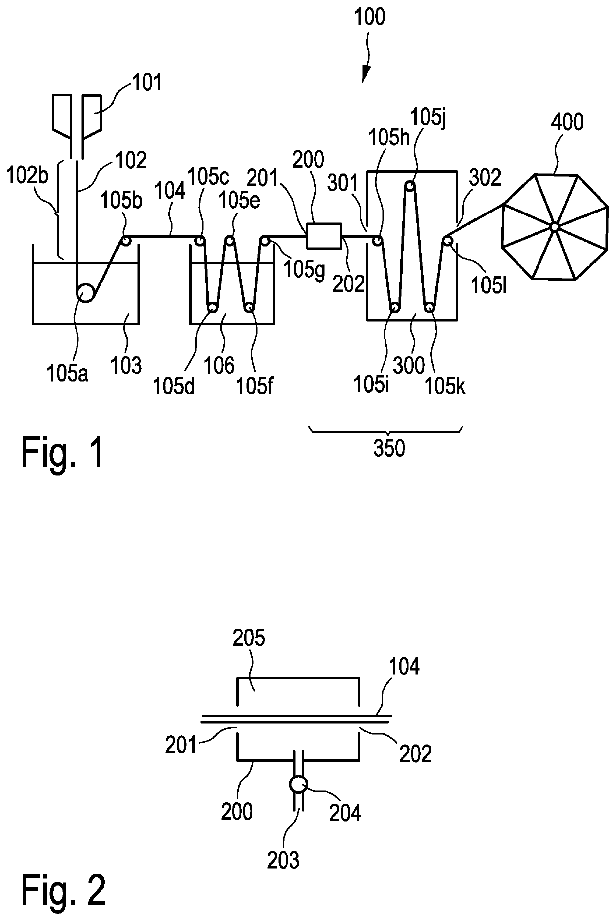
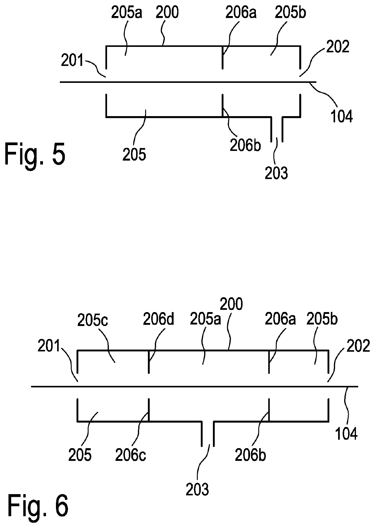
[0129]In contrast to comparison example 1, in example 1 the group of 16 hollow fiber membranes was guided through a pressure chamber in accordance with the embodiment according to FIG. 10, after passing through the rinsing baths and before being introduced into the tempering chamber. Air was introduced via the gas inlet of the pressure chamber so that a pressure of 3000 hPa was created in the central conical cavity of the pressure chamber, a pressure of 1500 hPa in the second conical cavity of the pressure chamber and a pressure of 1300 hPa in the third conical cavity of the pressure chamber. The dried hollow fiber membranes were wound up and examined as regards any possible defects. The manufacture of the hollow fiber membranes according to example 1 was carried out at different draw-off speeds. According to this, no fiber damage was found at a draw-off speed of 650 mm / s. The term draw-off speed is intended to refer to the speed at which the hollow fiber membrane passes through the...


PUM

PropertyMeasurementUnit
Temperatureaaaaaaaaaa
Pressureaaaaaaaaaa

Abstract

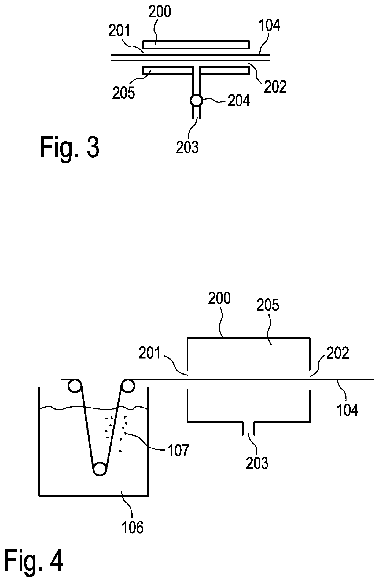
The invention relates to an apparatus and a method for the manufacture of at least one hollow fiber membrane, wherein a spinning mass is extruded via a spinning unit to form a spinning thread and precipitated in a precipitation bath to form a hollow fiber membrane and the hollow fiber membrane is optionally rinsed in a rinsing bath, wherein furthermore the hollow fiber membrane is passed through at least one drying unit, wherein the drying unit comprises a pressure section which is constructed in such a way that a positive pressure compared with atmospheric pressure can be set in the pressure section, and at least part of the precipitating agent or rinsing agent contained in the at least one hollow fiber membrane (104) is separated from the at least one hollow fiber membrane.

Description

TOPIC[0001]The invention relates to an apparatus for the manufacture of hollow fiber membranes. In particular, the invention relates to an apparatus for the manufacture of hollow fiber membranes, wherein the apparatus comprises an improved drying unit.[0002]In further aspects, the invention relates to methods for the manufacture of hollow fiber membranes. In particular, the invention relates to methods for the manufacture of hollow fiber membranes with an improved drying process of the hollow fiber membranes.BACKGROUND OF THE INVENTION[0003]Hollow fiber membranes are widely used in filtration technology. Hollow fiber membranes are used in particular in medical technology, e. g. in dialysis, in order to remove harmful metabolites from the blood of patients with kidney disease. Hollow fiber membranes are also used in water treatment in order to treat contaminated water. For such applications, the hollow fiber membranes are built into hollow fiber membrane filters, as they are referred...

Claims


Application Information

Patent Timeline
IPC IPC(8): B01D69/08B01D63/02
CPCB01D69/088B01D63/021B01D2323/08B01D2323/10B01D2323/42B01D67/0018B01D67/0095B01D69/087B01D63/0233B01D2323/081B01D69/0871
Inventor PAUL, MICHAEL
Owner FRESENIUS MEDICAL CARE DEUTSCHLAND GMBH
Learn More