
Control Device and Control Method for an Electrostatic Filter With a Configurable Number of Parallel and Serial Filter Zones

Active Publication Date: 2009-10-22
SIEMENS ENERGY GLOBAL GMBH & CO KG
View PDF18 Cites 10 Cited by
  • Summary
  • Abstract
  • Description
  • Claims
  • Application Information

AI Technical Summary

Benefits of technology

[0012]For the purposes of the invention, classes can also be defined using optimization programs of the client modules, wherein one or more precipitator zones of the electrostatic precipitator can be represented by means of said classes. Using the above described control entity and / or the corresponding control method for electrostatic precipitators, it is possible to achieve a significant improvement in performance compared with the prior art by means of more effective data transmission between the individual parts of the control device. The standard class definitions which are present in the server component are available for all client modules of the control entity. This results in a significant reduction in resource requirements. Expansion of the class definitions is simplified because changes need only be made in the field of the server component, thereby achieving a significant reduction in development time. The server component functions as a virtual software platform, whereas the client modules contain the “intelligence”. A lower susceptibility to software error is achieved by virtue of more rigorous data encapsulation, thereby resulting in higher software quality. According to the invention, it is particularly easy to realize the optimization of a plurality of electrostatic precipitators by means of one or more of the client modules used for optimization.

Problems solved by technology

If there is a plurality of electrostatic precipitators, the complexity of these management tasks increases drastically.
The checking effort involved in verification of the functionality of the software increases significantly, since it is not possible using justifiable effort to check all conceivable configurations.

Method used


Image

  • Control Device and Control Method for an Electrostatic Filter With a Configurable Number of Parallel and Serial Filter Zones
  • Control Device and Control Method for an Electrostatic Filter With a Configurable Number of Parallel and Serial Filter Zones
  • Control Device and Control Method for an Electrostatic Filter With a Configurable Number of Parallel and Serial Filter Zones

Examples


Embodiment Construction

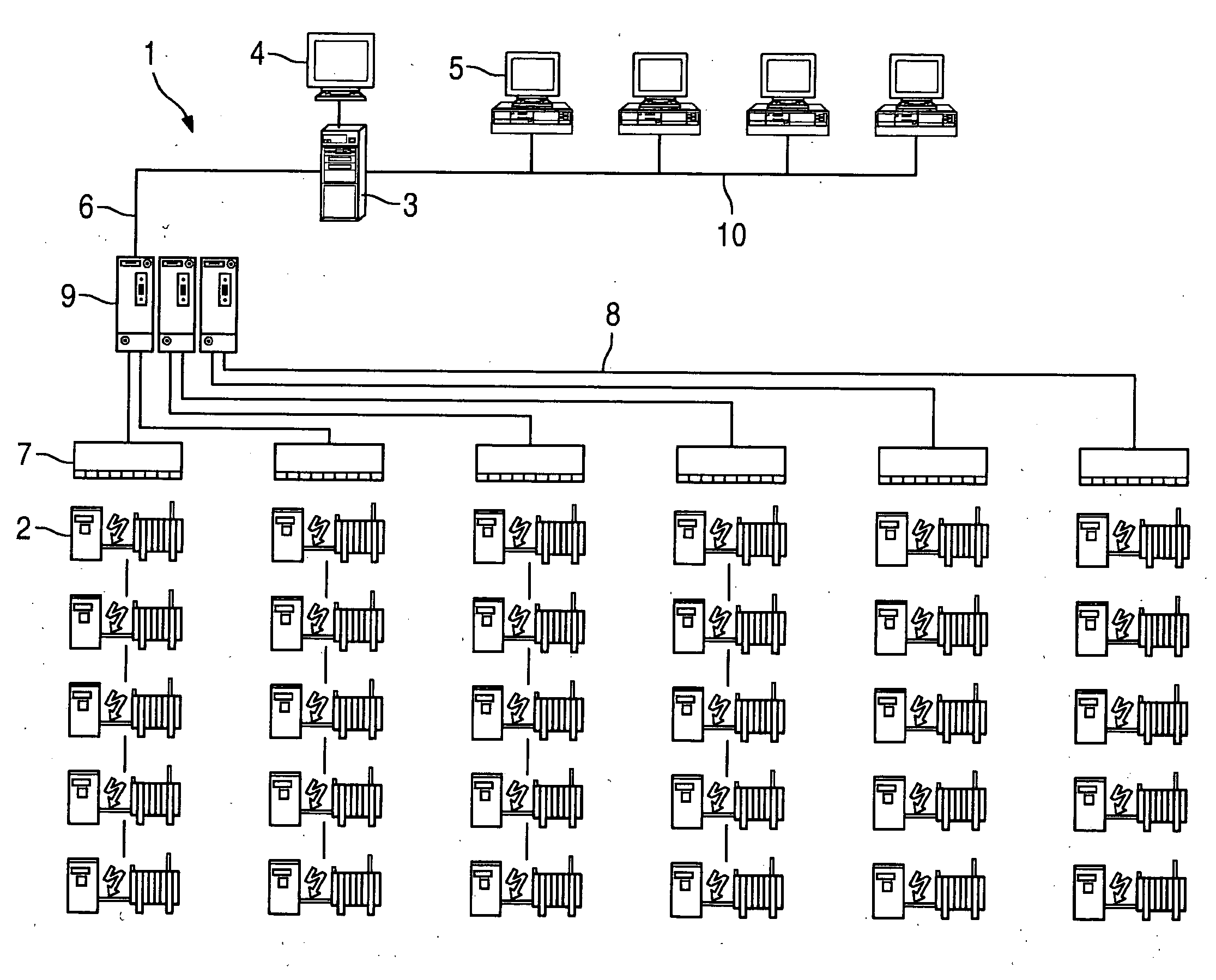
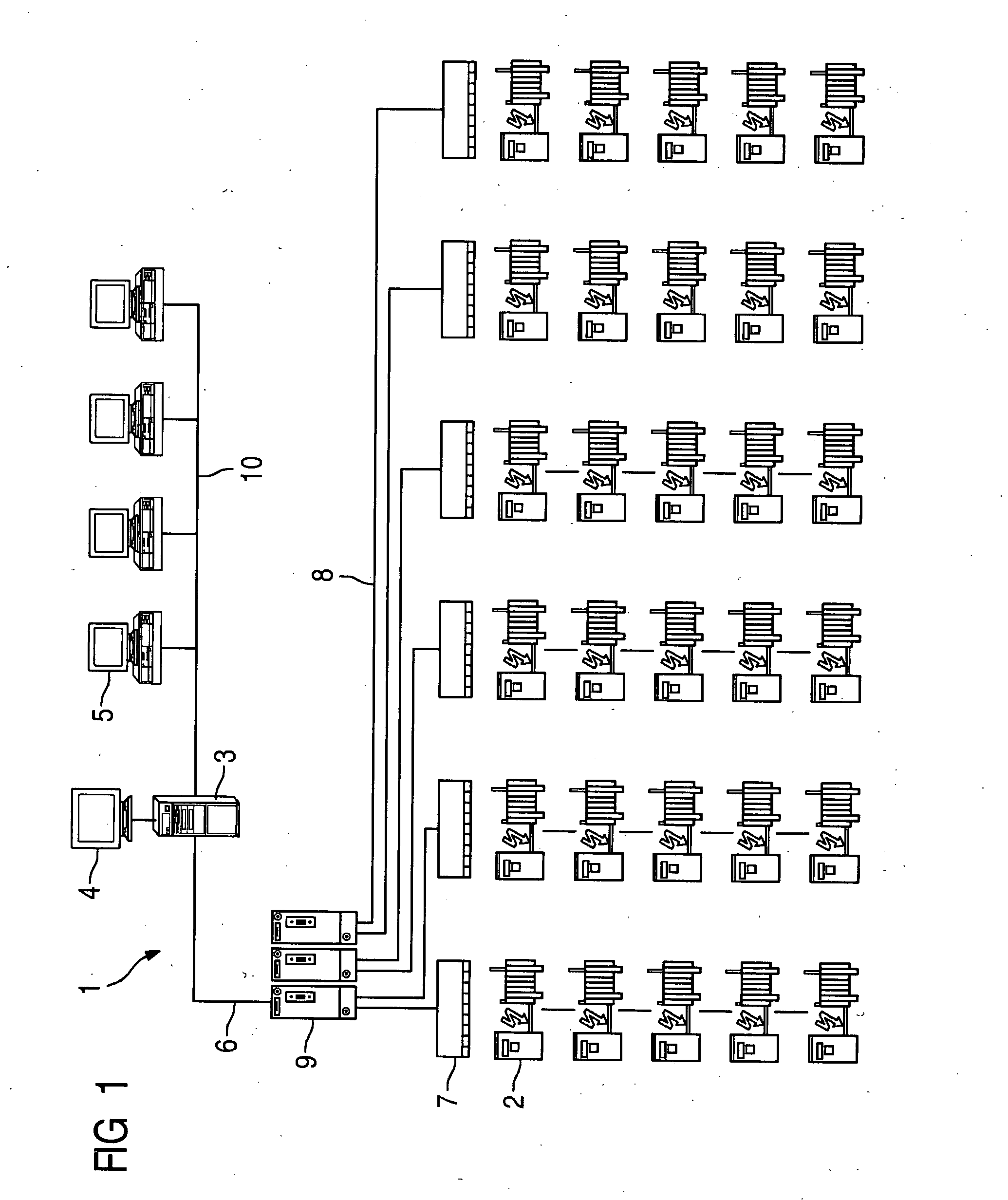
[0016]FIG. 1 shows an embodiment of a control entity 1 for electrostatic precipitators including a configurable number of parallel and serial precipitator zones, each of which is assigned a high-voltage supply unit 2 and auxiliary functional units (not shown in the figure), said control entity having a server component 3 with a monitor 4 and—in the illustrated exemplary embodiment—four client modules 5.

[0017]The server component 3 is connected to the high-voltage supply units 2 via a Profibus network 6. For this, a bus coupler 7 is assigned in each case to a group of—in the illustrated exemplary embodiment—five high-voltage supply units 2 with controllers. The—in the illustrated exemplary embodiment—six bus couplers 7 are connected via an optical Profibus 8 to optical interface modules 9, which in turn are connected to the server component 3.

[0018]The server component 3 with the—in the illustrated exemplary embodiment—four client modules 5 forms a second network 10 which is designed...


PUM


Abstract

The aim of the invention is to be able to adapt an item of visualization or optimization software with the least possible amount of effort made on any electrostatic filter configurations. To this end, the invention provides that the electrostatic filter, the high-voltage supply units, and the auxiliary functional units can be used by the software modules in the server component as objects with characteristic features and with characteristic methods, that are capable of being accessed as information, which only exists in the server component, for the client modules via data interfaces.

Description

CROSS REFERENCE TO RELATED APPLICATIONS[0001]This application is the U.S. National Stage of International Application No. PCT / EP2005 / 053557, filed Jul. 21, 2005 and claims the benefit thereof. The International Application claims the benefits of German application No. 10 2004 036 210.6 filed Jul. 26, 2004, both of the applications are incorporated by reference herein in their entirety.FIELD OF INVENTION[0002]The invention relates to a control entity for electrostatic precipitators including a configurable number of parallel and serial precipitator zones, each of which is assigned a high-voltage supply unit and auxiliary functional units, wherein said control entity features a server component and client modules and wherein different server modules are implemented in said control entity, said server modules allowing access to data of the electrostatic precipitator, the high-voltage supply units and the auxiliary functional units in order that said data can be visually displayed, stor...

Claims


Application Information

Patent Timeline
IPC IPC(8): B03C3/68G06F1/26
CPCB03C3/68Y10S323/903
Inventor GRASS, NORBERT
Owner SIEMENS ENERGY GLOBAL GMBH & CO KG
Learn More