
Fast close open

a control scheme and switch technology, applied in the direction of circuit arrangement, fault location by conductor type, parameter calibration/setting, etc., can solve the problems of shortening the outage duration of the customer, completely defeated, and increasing the cost and complexity of the switch

Active Publication Date: 2021-03-25
S&C ELECTRIC
View PDF0 Cites 7 Cited by
  • Summary
  • Abstract
  • Description
  • Claims
  • Application Information

AI Technical Summary

Benefits of technology

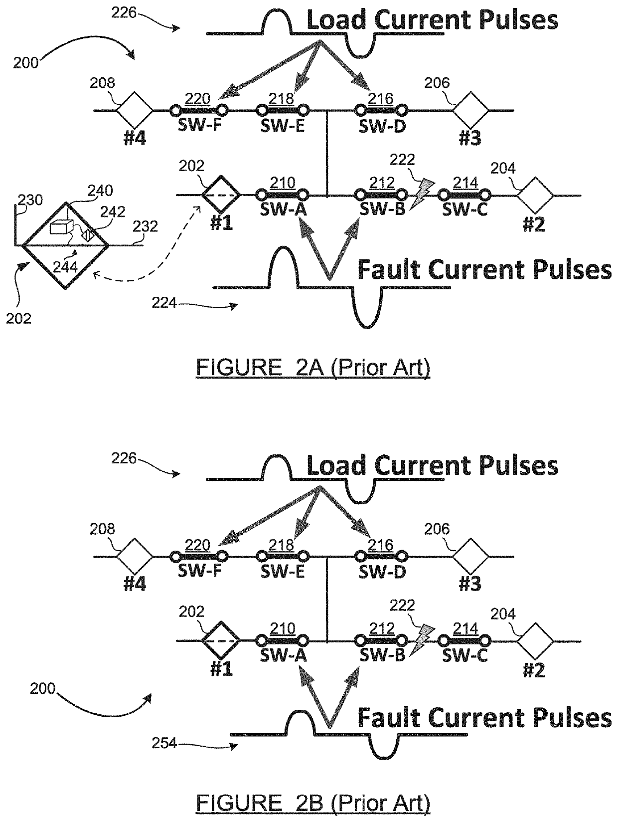
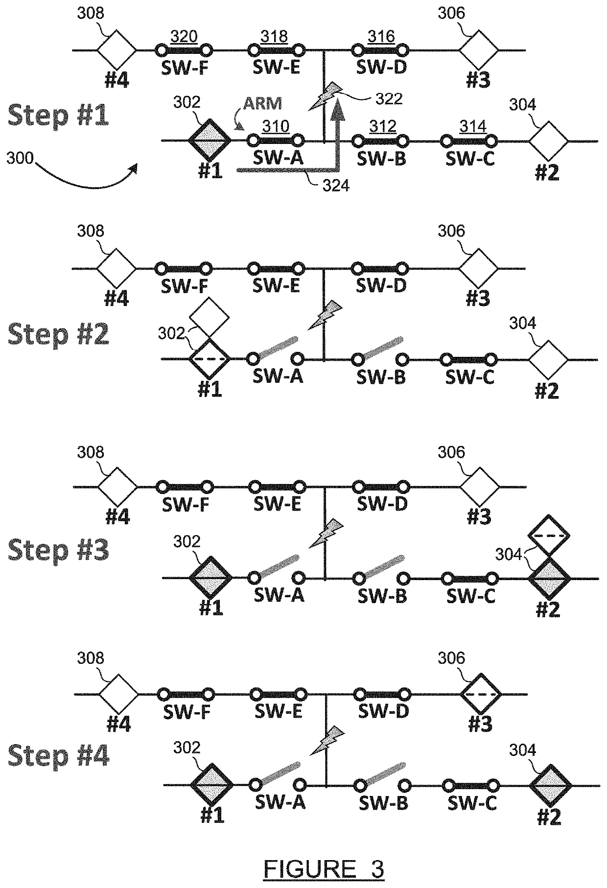
The present invention is about a control system and method for sectionalizing switches and pulse-testing interrupter / reclosers in a distribution grid. The method allows for fault location, isolation, and service restoration without using a separate communications infrastructure between the switches and a central controller. Switches enter an "armed state" when they experience a high fault current during an initial fault event. Then, an interrupter / recloser runs its test pulse sequence and counts any armed switches as fault pulse events, while non-armed switches count the test pulses as load pulse events. Switches open to isolate the fault based on threshold values of fault count and load count events. The invention allows for fast close-open events if necessary to arm remaining switches for proper fault-count opening.

Problems solved by technology

In addition, the fault isolation feature of the technology can help crews locate the trouble spots more quickly, resulting in shorter outage durations for the customers impacted by the faulted section.
Centralized FLISR systems, based on real-time communications, are effective when the communication channels are operable, but are completely defeated when communication is interrupted for any reason.
The communication system equipment requirements also add cost and complexity to the switches.
However, if the feeder source changes to an alternate, the pre-programmed sectionalizing switch behavior will result in incomplete or suboptimal fault isolation.
However, it can be difficult in some situations for a sectionalizing switch to distinguish between a fault current pulse and a load current pulse during the testing process.

Method used


Image

  • Fast close open
  • Fast close open
  • Fast close open

Examples


Embodiment Construction

[0016]The following discussion of the embodiments of the disclosure directed to a technique for isolating a fault in a feeder using sectionalizing switches, including arming switches and fast close-open events, is merely exemplary in nature, and is in no way intended to limit the disclosure or its applications or uses.

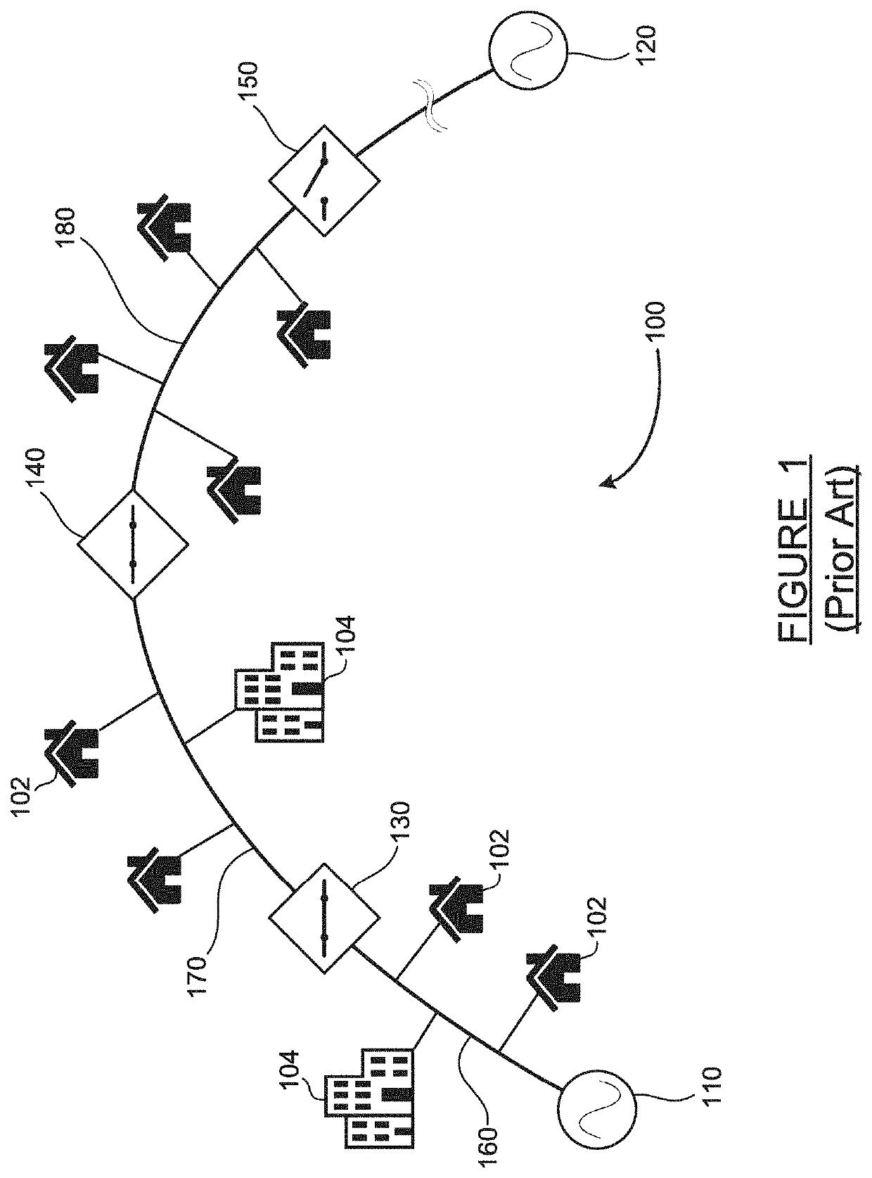
[0017]An electrical power grid consists of a transmission network and a distribution network. The transmission network handles the movement of high-voltage electrical energy from a generating site, such as a power plant, to an electrical substation. The distribution network moves medium-voltage electrical energy on local wiring between substations and customers. Because the distribution portion of the grid includes power lines which are exposed to many fault-inducing conditions including wind, lightning, ice and snow, contamination, tree contacts, pole damage from vehicle collisions, etc., faults occur on the distribution grid. Fault location, isolation and service res...


PUM


Abstract

A control system and method for sectionalizing switches and pulse-testing interrupter / reclosers in a distribution grid feeder which enables fault location, isolation and service restoration without requiring an external communications infrastructure to pass information between the switches. The method includes switches entering an armed state when they experience a high fault current during an initial fault event. Then, when the interrupter / recloser runs its test pulse sequence, any armed switch counts all test pulses as fault pulses, while non-armed switches count the test pulses as load pulses. Switches open to isolate the fault based on threshold values of fault pulse count and load pulse count. When an initially active interrupter / recloser completes its test pulse sequence, another interrupter / recloser begins its sequence, and all switches reconfigure their threshold values based on the new interrupter / recloser. Interrupter / reclosers after the initial device use a fast close-open event if necessary to arm some switches for proper fault-count opening.

Description

BACKGROUNDField[0001]The present disclosure relates generally to a control scheme for sectionalizing switches in an electrical grid feeder. More particularly, it relates to a system and method enabling automated sectionalizing switches equipped with only three-phase current sensing to isolate faults when upstream interrupter / reclosers are testing for continued fault presence.Discussion of the Related Art[0002]An electrical power transmission / distribution network, often referred to as an electrical grid, typically includes a number of power generation plants each including a number of power generator units, such as gas turbine engines, nuclear reactors, coal-fired generators, hydro-electric dams, etc. The grid may also include wind and / or solar energy generation farms. Not only are there many different types of energy generators on the grid, but there are many different types of loads, and the generators and loads are distributed over large geographic areas. The transmission grid car...

Claims


Application Information

Patent Timeline
Patent Type & Authority Applications(United States)
IPC IPC(8): H02H7/22G01R31/08H02H3/08H02H3/38H02H3/02H02H3/06H02H3/00
CPCH02H7/22G01R31/086H02H3/08H02H3/003H02H3/021H02H3/06H02H3/38H02H3/006H02H7/30H02H3/063H02H7/26
Inventor MEISINGER, MICHAELBISHOP, MARTINWILLIAMS, STEPHENPORTER, DAVID
Owner S&C ELECTRIC
Learn More