
System and Method for Wireless Power Transfer to a Rotating Member in a Motor

Active Publication Date: 2021-04-01
ROCKWELL AUTOMATION TECH
View PDF0 Cites 2 Cited by
  • Summary
  • Abstract
  • Description
  • Claims
  • Application Information

AI Technical Summary

Benefits of technology

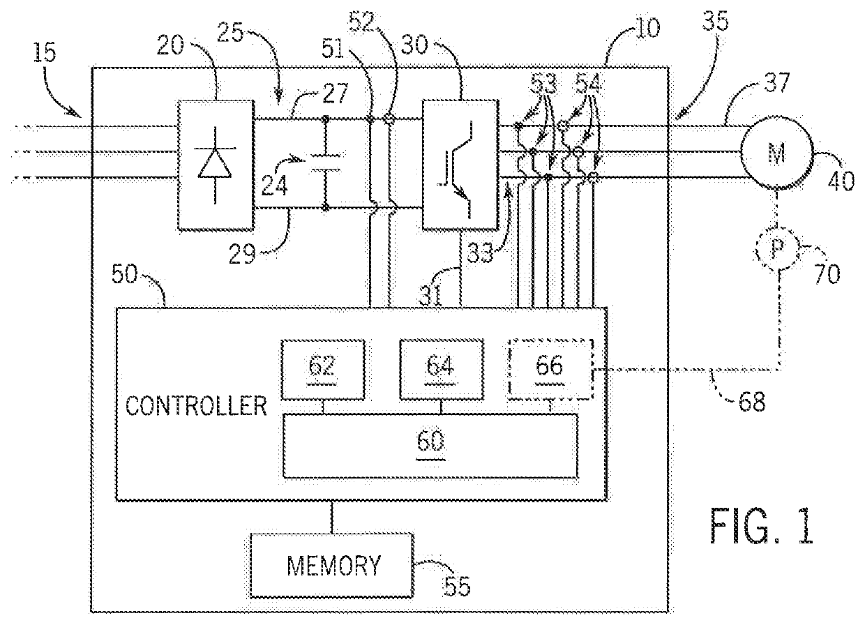
This patent describes a system to reduce losses in a motor caused by eddy currents. A pick-up coil is mounted on the rotor to interact with harmonic content in the voltage applied to the machine from the motor drive. This pick-up coil does not interfere with the desired operation of the machine and helps improve its performance by reducing eddy currents. The energy harvested by the pick-up coil can also be utilized for a useful function, such as powering a sensor or a resistive load. It can also be connected to an inductive-capacitive circuit to maximize power transfer.

Problems solved by technology

The current and voltage present at the harmonic frequencies induce undesirable eddy currents within the machine which, in turn, result in reduced performance or undesirable heat losses within the machine.

Method used


Image

  • System and Method for Wireless Power Transfer to a Rotating Member in a Motor
  • System and Method for Wireless Power Transfer to a Rotating Member in a Motor
  • System and Method for Wireless Power Transfer to a Rotating Member in a Motor

Examples


first embodiment

[0040]According to the invention, it is contemplated that the pick-up coil 48 may be used to reduce the undesirable effects of the harmonic content on the motor 40. Turning next to FIG. 6, the pick-up coil 48 may be connected to a resistive load 72. For a purely resistive load, the voltage induced in the pick-up coil 48 is dissipated in the load 72 as heat and a resultant current flows through the pick-up coil 48 as defined by Ohm's law. Because energy is dissipated in a resistive load 72 as heat, the resistive load 72 may be mounted to a heat sink 74 within the motor. The resistive load 72 and heat sink 74 may be located within the motor 40 at a desirable location in which to dissipate heat. According to the illustrated embodiment, the resistive load 72 and heat sink 74 are mounted proximate the output end of the motor. The output end of the motor is commonly mounted to a drive train or directly to a controlled object, such that a substantial physical element, such as a gearbox, le...

second embodiment

[0043]According to the invention, it is contemplated that the pick-up coil 48 may be connected to a circuit 92 mounted on the rotor 45 and serves as a wireless power source for the circuit. With reference next to FIG. 7, a circuit board 90 has a generally circular form with an opening extending through the center and is mounted on the rotor 45. A circuit 92, illustrated as a single block mounted to one side of the circuit board 90 may include multiple electronic components according to an application's requirements, The circuit 92 may include a power converter configured to receive the AC voltage induced on the pick-up coil 48 as an input and to provide a second voltage as an output. The power converter may include, for example, diodes arranged as a passive rectifier to convert the AC voltage to a DC voltage. The power converter may also include a capacitance connected to the output of the passive rectifier in order to reduce a ripple present on the DC voltage from rectification. Op...


PUM


Abstract

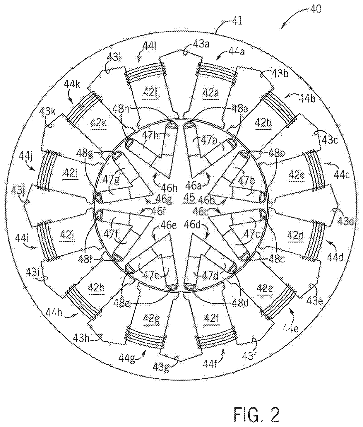
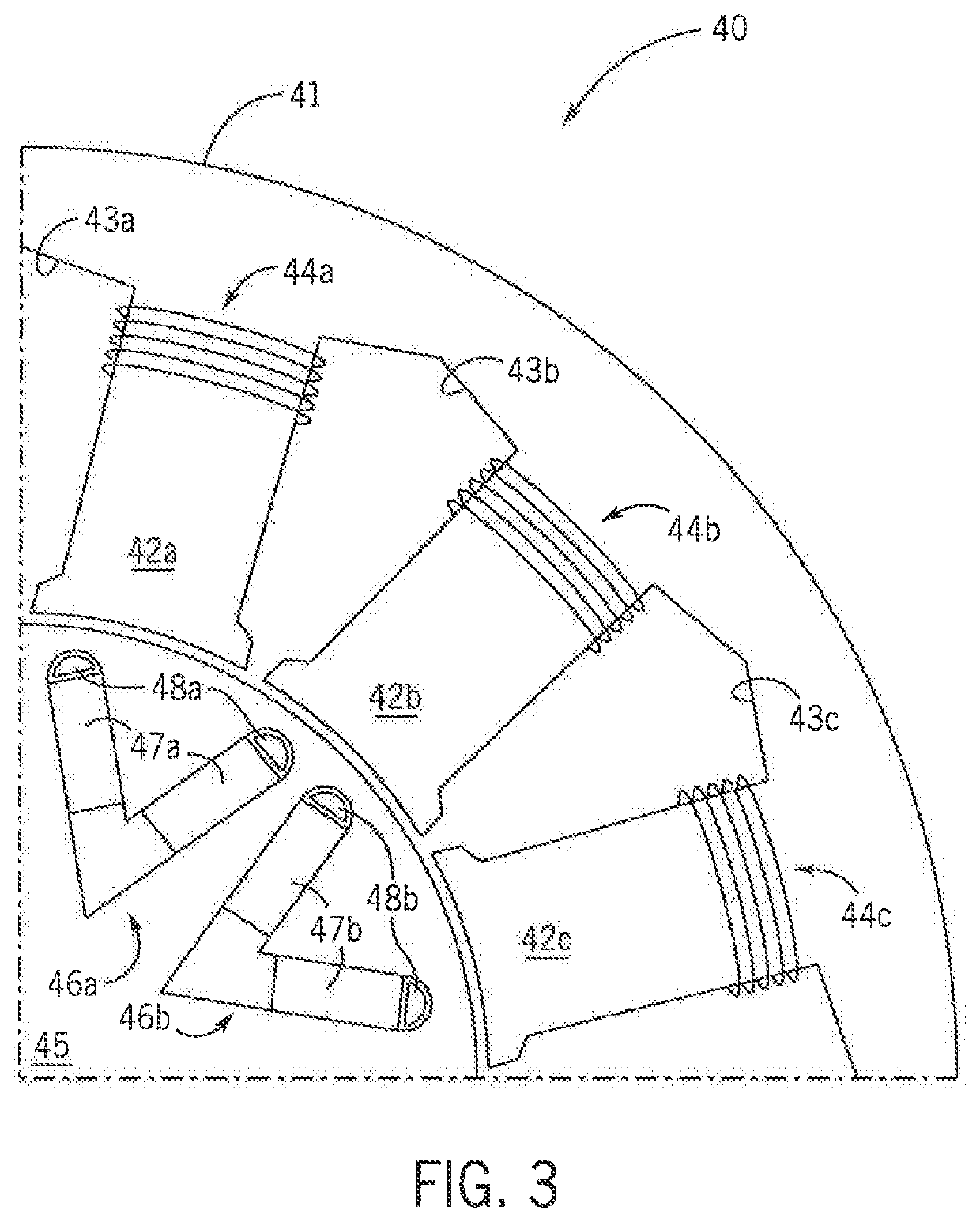
A system to reduce eddy currents and the resulting losses in a synchronous motor includes at least one pick-up coil mounted to the rotor. Each pick-up coil may be located proximate a pole on the rotor. A voltage applied to the stator to control the synchronous motor includes both a fundamental component and harmonic components. The fundamental component interacts with a magnetically salient structure in each pole on the rotor to cause rotation of the rotor. The harmonic components induce a voltage in the pick-up coil. The portion of the harmonic components that induce a voltage in the pick-up coil no longer generate eddy currents within the motor. The energy harvested by the pick-up coil may also be utilized in a function other than driving the motor, such as powering a sensor mounted on the rotor.

Description

BACKGROUND INFORMATION[0001]The subject matter disclosed herein relates generally to harvesting energy transferred between a stator and a rotor in a rotating machine and, more specifically, to a system which utilizes a pick-up coil mounted on the rotor in a synchronous machine to harvest energy from harmonic content present in the stator of the machine.[0002]As is known to those skilled in the art, a traditional synchronous machine utilizes a coil in the stator and a. magnetic saliency in the rotor to control rotation of the motor. In a permanent magnet synchronous machine, magnets are mounted on the surface or embedded in the rotor and generate a magnetic field that interacts with an electromagnetic field generated by a controlled voltage applied to the coil in the stator. The controlled voltage has a variable magnitude and a variable frequency and generates the electromagnetic field which rotates within the motor according to the variable frequency to control rotation of the rotor...

Claims


Application Information

Patent Timeline
IPC IPC(8): H02K3/42H02K1/24H02J50/10
CPCH02K3/42H02J50/10H02K1/24H02K21/16H02K1/223H02K19/10H02K1/246H02J50/001H02K1/16
Inventor SUN, XIKAISIZOV, GENNADIMELFI, MICHAEL J.
Owner ROCKWELL AUTOMATION TECH
Learn More