Display device and drive method thereof

Active Publication Date: 2021-04-08
SHARP KK
View PDF0 Cites 2 Cited by
  • Summary
  • Abstract
  • Description
  • Claims
  • Application Information

AI Technical Summary

Benefits of technology

[0015]According to the above display device and the drive method of the display device, by performing control, in the normal state, for making the plurality of scanning line drive circuits operate in turn, and performing control, in the abnormal state, for stopping the operation of the

Problems solved by technology

As a result, the scanning line drive circuit may not be able to transfer the pulse correctly.
As a result,

Method used


Image

  • Display device and drive method thereof
  • Display device and drive method thereof
  • Display device and drive method thereof

Examples


first embodiment

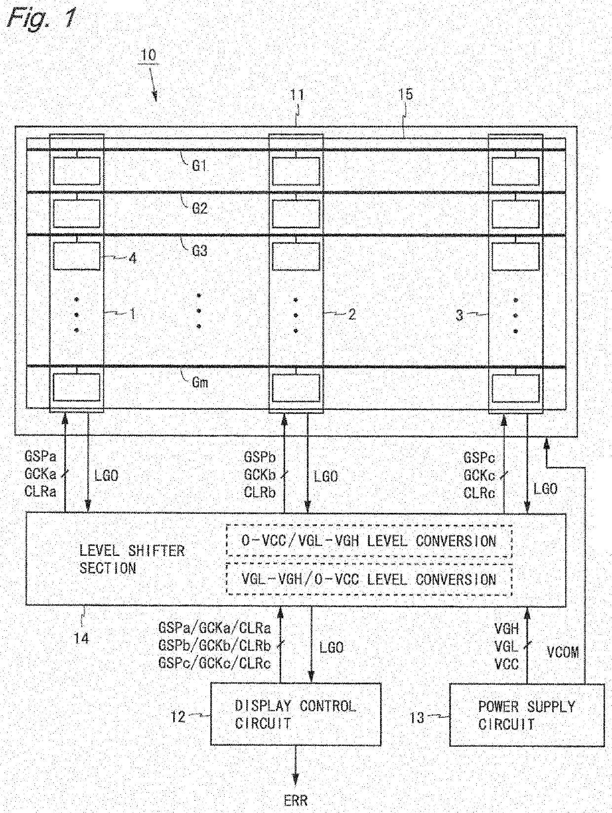
[0035]FIG. 1 is a block diagram showing a configuration of a liquid crystal display device according to a first embodiment. A liquid crystal display device 10 shown in FIG. 1 includes a liquid crystal panel 11, a display control circuit 12, a power supply circuit 13, and a level shifter section 14. In the following, a horizontal direction of the drawings is referred to as a row direction, and a vertical direction of the drawings is referred to as a column direction. It is assumed that m is an integer not less than 2, and i is an integer not less than 1 and not more than m.

[0036]A pixel area 15 is set to the liquid crystal panel 11. Inside the pixel area 15, m scanning lines G1 to Gm, a plurality of data lines (not shown), and a plurality of pixel circuits (not shown) are formed. The scanning lines G1 to Gm extend in the row direction and are arranged in parallel with each other. The data lines extend in the column direction and are arranged in parallel with each other so as to inter...

second embodiment

[0063]A liquid crystal display device according to a second embodiment has the same configuration as that of the liquid crystal display device 10 according to the first embodiment (see FIG. 1). In the abnormal state, the display control circuit according to the present embodiment performs control different from that performed by the liquid crystal display device 10 according to the first embodiment. Among components of each embodiment described below, same components as those described in any preceding embodiment are provided with the same reference numbers and description thereof is omitted.

[0064]In a liquid crystal display device having a plurality of GDM circuits, when an abnormality occurs in a certain GDM circuit, it is presumed that other GDM circuits deteriorate to a same degree. Thus, in the abnormal state, the liquid crystal display device according to the present embodiment displays a screen using a frame rate lower than that in the normal state. Specifically, in the abnor...

third embodiment

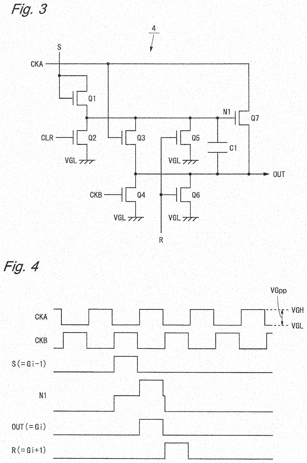
[0068]FIG. 11 is a block diagram showing a configuration of a liquid crystal display device according to a third embodiment. A liquid crystal display device 20 shown in FIG. 11 is obtained by replacing the display control circuit 12 and the power supply circuit 13 in the liquid crystal display device 10 according to the first embodiment with a display control circuit 22 and a power supply circuit 23, respectively. In the following, a difference between the high-level voltage VGH and the low-level voltage VGL output from the power supply circuit 23 is referred to as an amplitude VGpp of a power supply voltage (see FIG. 4).

[0069]The display control circuit 22 is obtained by adding to the display control circuit 12, a function of outputting a power supply control signal PC. The power supply control signal PC is a signal indicating the state of the scanning line drive circuits, and indicates whether an abnormality occurs in the first to third GDM circuits 1 to 3. For example, the power ...


PUM


Abstract

In a display device including a display panel, a plurality of scanning line drive circuits formed on the display panel, each driving scanning lines individually, and a display control circuit, the scanning line drive circuit outputs a state signal, and the display control circuit determines whether a state is normal based on the state signal, performs control, in a normal state, for making the plurality of scanning line drive circuits operate in turn, and performs control, in an abnormal state, for stopping an operation of an abnormal scanning line drive circuit and for making a normal scanning line drive circuit operate in turn. A last-stage output signal of the scanning line drive circuit is used as the state signal. With this, a display device capable of lengthening time until an abnormality occurs and keeping display quality even when the abnormality occurs is provided.

Description

TECHNICAL FIELD[0001]The present invention relates to a display device, and more particularly relates to a display device having a plurality of scanning line drive circuits and a drive method thereof.BACKGROUND ART[0002]Liquid crystal display devices are widely used as thin, light-weight, and low power consumption display devices. A liquid crystal panel provided to the liquid crystal display device includes a plurality of scanning lines, a plurality of data lines, and a plurality of pixel circuits. The liquid crystal display device is provided with a scanning line drive circuit which drives the scanning lines and a data line drive circuit which drives the data lines. The scanning line is also called a gate line, and the scanning line drive circuit is also called a gate driver.[0003]In the liquid crystal display device, in order to downsize the device, a method of forming the scanning line drive circuit together with the pixel circuits on the liquid crystal panel may be adopted. This...

Claims


Application Information

Patent Timeline
IPC IPC(8): G09G3/36
CPCG09G3/3677G09G3/3655G02F1/133G09G3/3674G09G2310/08G09G2310/0289G09G3/3696
Inventor UENO, KOHJI
Owner SHARP KK
Why Eureka
Try Eureka