Bending operation mechanism of endoscope, and endoscope

Pending Publication Date: 2021-04-22
OLYMPUS CORP
View PDF0 Cites 2 Cited by
  • Summary
  • Abstract
  • Description
  • Claims
  • Application Information

AI Technical Summary

Benefits of technology

The present invention provides a bending operation mechanism for an endoscope that includes multiple wires and rotation members. The mechanism allows the bending portion of the endoscope to bend in two directions when pulled by the wires. The operation member can rotate in two directions to engage with the rotation members and pull the wires. The design ensures that the rotation members and the operation member do not interfere with each other when the operation member is rotated in the opposite directions. The technical effects of this design include improved flexibility, better control, and reduced friction during bending operations.

Problems solved by technology

Pulling the wire by operating an angle operation knob for rotating the pulley causes tension in the wire, and the tension causes the bending portion to bend.
Pulling the one end side of the wire connected to the pulley may cause the other end side to loosen in such a bending operation mechanism.

Method used


Image

  • Bending operation mechanism of endoscope, and endoscope
  • Bending operation mechanism of endoscope, and endoscope
  • Bending operation mechanism of endoscope, and endoscope

Examples


embodiment 1

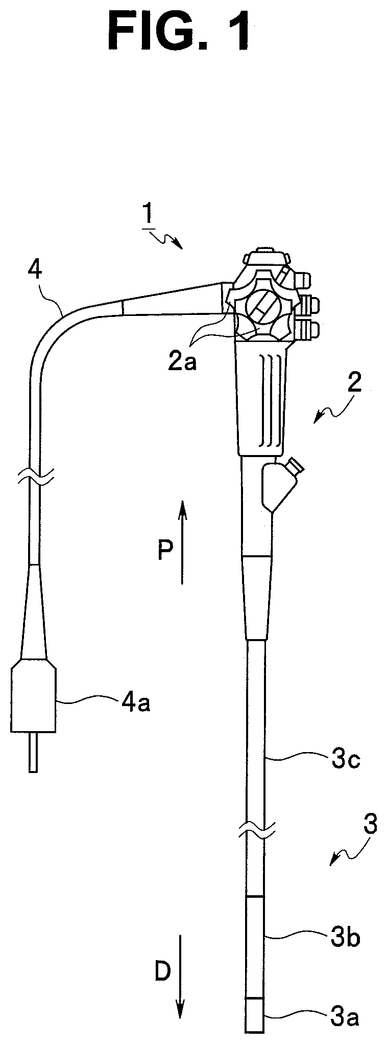
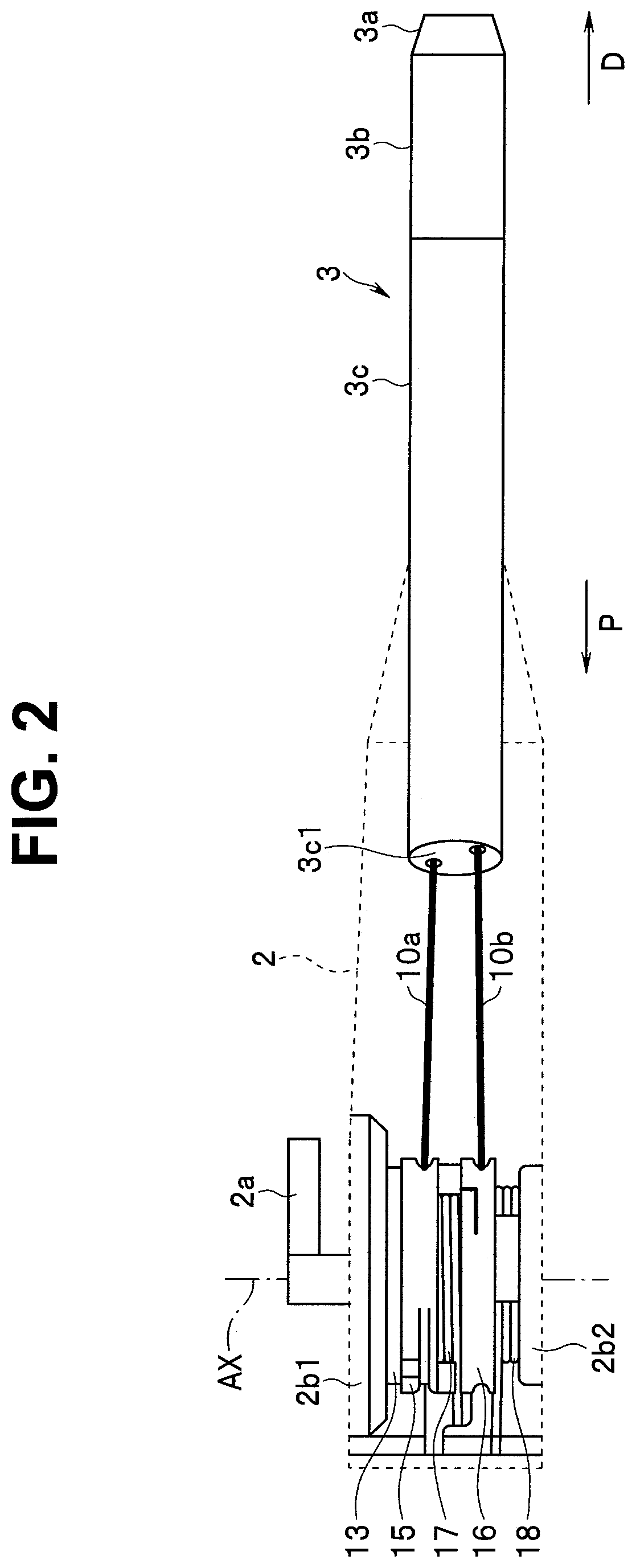
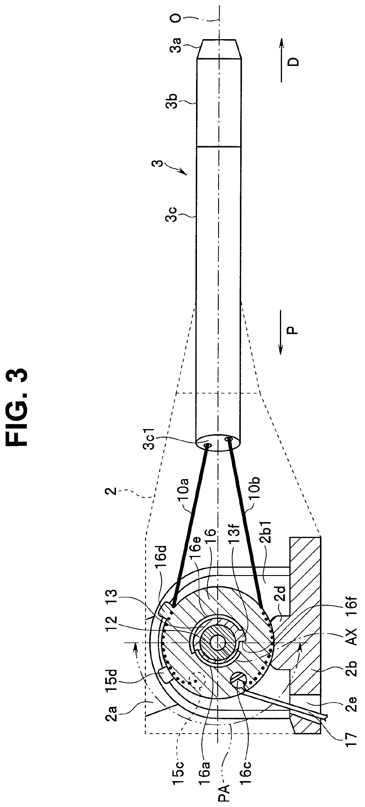
[0024]FIG. 1 to FIG. 9 illustrate Embodiment 1 of the present invention, and FIG. 1 is a front elevational view illustrating a configuration of an endoscope 1.

[0025]The endoscope 1 is capable of being introduced into a subject, and is used for optically observing the inside of the subject. The subject into which the endoscope 1 is introduced is an object to be observed, and may be any of a human body, a living body other than a human body, and an artifact. Some examples of artifacts are such as machines and buildings.

[0026]In the present embodiment, the case where the endoscope 1 is an electronic endoscope that picks up an optical image of a subject will be described as an example, but the present invention is not limited thereto, and may be applied to an optical endoscope for observing an optical image.

[0027]The endoscope 1 is provided with an operation portion 2, an insertion portion 3, and a universal cord 4.

[0028]The operation portion 2 is a portion for a user to grasp and perfo...

embodiment 2

[0079]FIG. 10 to FIG. 14 illustrate Embodiment 2 of the present invention, and FIG. 10 is a diagram illustrating a configuration of a bending operation mechanism of the endoscope 1.

[0080]In the Embodiment 2, the same components as those in the Embodiment 1 described above are denoted by the same reference numerals, and description thereof will appropriately be omitted, and only differences will be mainly described.

[0081]In the Embodiment 1 described above, the bending direction of the bending portion 3b is the up-down direction (or right-left direction), i.e., two directions, but in the present embodiment, the bending direction of the bending portion 3b is the up-down direction and the right-left direction, i.e., four directions. The present embodiment consequently has a configuration in which the combination of the bending in the up-down direction and the bending in the right-left direction enables the bending in any direction around the insertion axis O.

[0082]To achieve the config...


PUM


Abstract

A bending operation mechanism of an endoscope including: a first pulley configured to pull a first wire by being rotated in a first rotation direction; a second pulley, which is coaxial with the first pulley, configured to pull a second wire by being rotated in a second rotation direction opposite to the first rotation direction; and a rotation shaft member including a first protrusion that engages only with the first engagement portion of the first pulley when the rotation shaft member is rotated in the first rotation direction from a neutral position when a bending portion is not bent and a second protrusion that engages only with the second engagement portion of the second pulley when the rotation shaft member is rotated in the second rotation direction from the neutral position.

Description

CROSS REFERENCE TO RELATED APPLICATION[0001]This application is a continuation application of PCT / JP2019 / 006816 filed on Feb. 22, 2019 and claims benefit of Japanese Application No. 2018-093035 filed in Japan on May 14, 2018, the entire contents of which are incorporated herein by this reference.BACKGROUND OF THE INVENTION1. Field of the Invention[0002]The present invention relates to a bending operation mechanism of an endoscope for bending a bending portion by pulling a wire, and an endoscope.2. Description of the Related Art[0003]A bending operation mechanism using a wire in an endoscope has a configuration in which the distal end portion of the wire is connected to a bending portion of the endoscope, and the proximal end portion of the wire is connected to a pulley provided to an operation portion. Pulling the wire by operating an angle operation knob for rotating the pulley causes tension in the wire, and the tension causes the bending portion to bend.[0004]Pulling the one end ...

Claims


Application Information

Patent Timeline
IPC IPC(8): A61B1/005
CPCA61B1/0057A61B1/0052G02B23/24
Inventor YOSHINAGA, TAKUTOOTA, TSUKASAWANG, XIONGWEI
Owner OLYMPUS CORP
Why Eureka
Try Eureka