Turbo compressor

a compressor and turbine technology, applied in the direction of liquid fuel engines, lighting and heating apparatus, heating types, etc., can solve the problems of limited commercialization of bearingless motors, and achieve the effects of reducing the force of reducing the force, reducing the cost of the controller, and easy control of two magnetic bearings

Pending Publication Date: 2021-04-22
DAIKIN IND LTD
View PDF5 Cites 6 Cited by
  • Summary
  • Abstract
  • Description
  • Claims
  • Application Information

AI Technical Summary

Benefits of technology

[0093]According to the sixteenth aspect, it is possible to easily control two magnetic bearings.
[0094]According to the seventeenth aspect, it is possible to more reliably achieve the advantages described above.
[0095]According to the eighteenth aspect, with the use of controllers that provide optimum computational speeds and output capacities for translational-direction control and tilt-direction control, it is possible to reduce the cost of the controllers.
[0096]According to the nineteenth to twenty-second aspects, the magnetic bearings handle not only a force for reducing a tilt displacement angle but also a portion of a force for reducing a displacement in the translational direction. This can reduce the force for reducing the force to be output from the bearingless motor to reduce a displacement in the translational direction. It is possible to reduce the size of the bearingless motor.
[0097]According to the twenty-third to twenty-seventh aspects, the gas bearing supports at least a portion of the radial load of the drive shaft. This can reduce the radial load imposed on the bearingless motor. Thus, it is possible to increase the driving torque output of the bearingless motor.
[0098]According to the twenty-third to twenty-seventh aspects, the axial length of a rotating system including the bearingless motor, the gas bearing, and the drive shaft can be set to be small. Thus, it is possible to expand a region in which the turbo compressor can be operated safely.

Problems solved by technology

Commercialization of the bearingless motor is hitherto limited to applications in which the surging phenomenon is less likely to occur.

Method used


Image

  • Turbo compressor
  • Turbo compressor
  • Turbo compressor

Examples


first embodiment

Modification of First Embodiment

[0199]A modification of the first embodiment will be described. This modification is different from the first embodiment in a current corresponding to an upper limit of a predetermined current range.

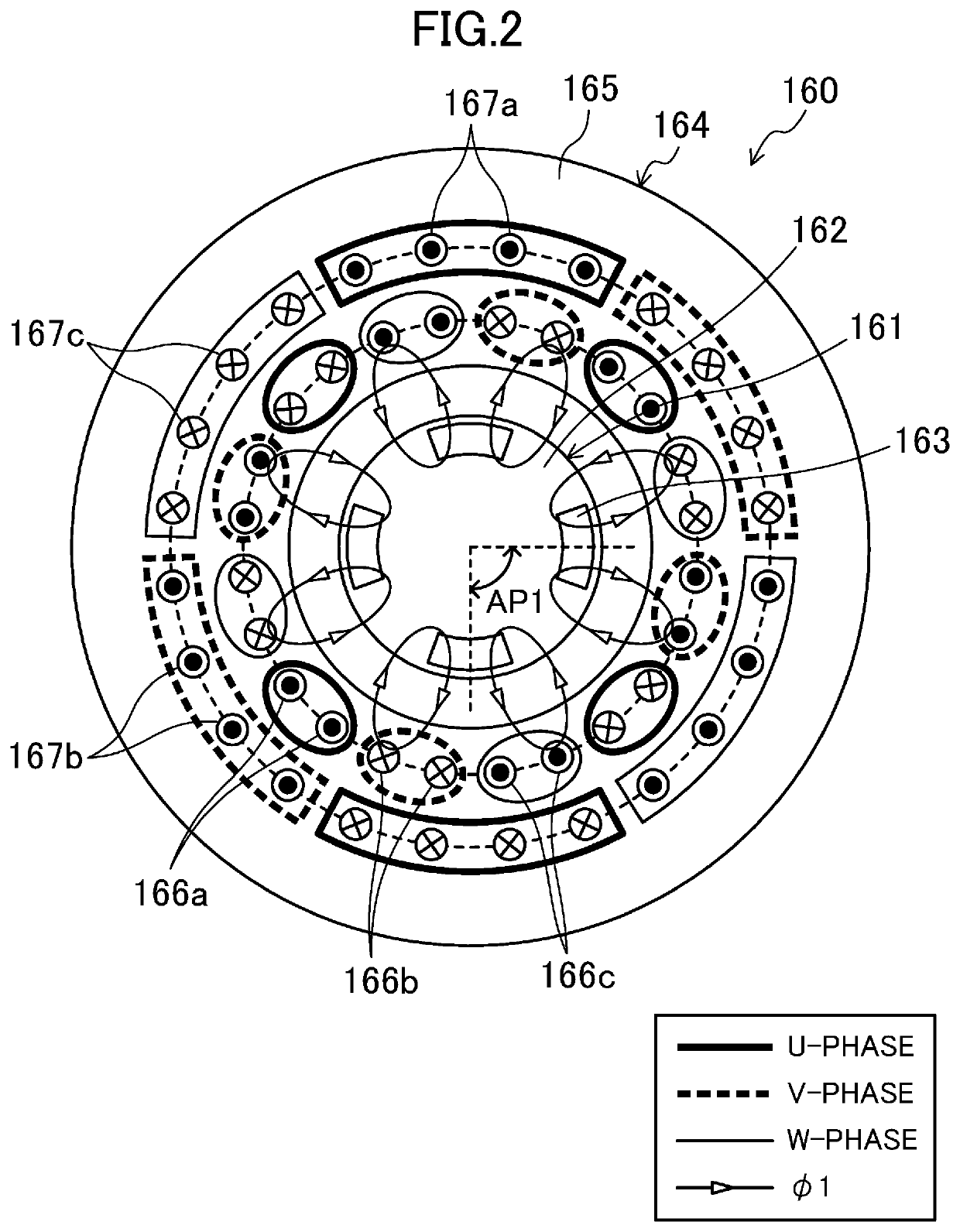
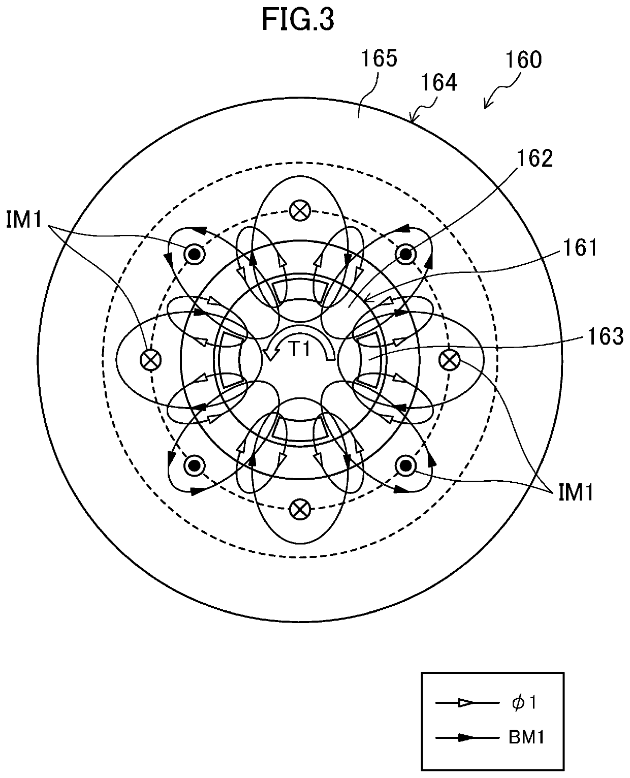
[0200]In this modification, a current corresponding to an upper limit of a predetermined current range is a current obtained by adding together the maximum torque current IBMmax and the maximum support force current IBSmax. In this modification, the first and second bearingless motors (160, 170) are configured such that a magnetic flux BMSmax generated in the first and second bearingless motors (160, 170) by causing a total of current obtained by adding together the maximum torque current IBMmax and the maximum support force current IBSmax to flow through the coils (166a to 166c, 167a to 167c, 176a to 176c, 177a to 177c) of the first and second bearingless motors (160, 170) becomes less than BMmax+BSmax (BMSmax160, 170), a magnetic saturation is considered...

second embodiment

of Invention

[0202]A second embodiment of the present invention will be described. In a turbo compressor (101) according to this embodiment, the drive support unit has a different configuration from that in the first embodiment. The following description mainly focuses on differences from the first embodiment.

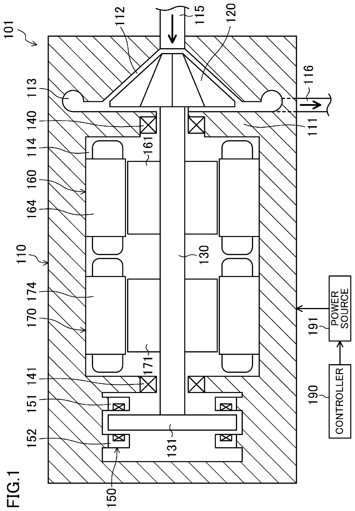
[0203]As illustrated in FIG. 8, the turbo compressor (101) according to this embodiment includes one radial magnetic bearing (180) and one bearingless motor (170), in place of the first and second bearingless motors (160, 170). The radial magnetic bearing (180) and the bearingless motor (170) constitute a drive support unit.

[0204]The radial magnetic bearing (180) is arranged in a portion of the electric motor chamber (114) closer to the impeller (120), and the bearingless motor (170) is arranged in a portion of the electric motor chamber (114) farther from the impeller (120). The configuration of the bearingless motor (170) is similar to the configuration of the second bearingle...

third embodiment

Advantages of Third Embodiment

[0239]As described above, in the electric motor system (230) according to this embodiment, rotational driving and contactless supporting of the drive shaft (240) are performed using the bearingless motor (250) and the radial magnetic bearing (260). This configuration can reduce the size of the electric motor system (230), compared to a case where a motor that performs only rotational driving of the drive shaft (240) and a magnetic bearing that performs only contactless supporting of the drive shaft (240) are provided in place of the bearingless motor (250). Specifically, the length of the drive shaft (240) can be reduced.

[0240]In the electric motor system (230) according to this embodiment, furthermore, the radial load supported by the radial magnetic bearing (260) is larger than the radial load supported by the bearingless motor (250). That is, the radial magnetic bearing (260) is arranged at a position at which the radial load of the drive shaft (240)...


PUM


Abstract

A drive support unit of a turbo compressor includes at least one bearingless motor. The at least one bearingless motor includes a rotor-stator pair constituted by a rotor and a stator, and is configured to rotationally drive a drive shaft and to support a radial load of the drive shaft in a contactless manner. Accordingly, it is possible to provide a turbo compressor to which a bearingless motor is applied.

Description

BACKGROUND OF THE INVENTION1. Field of the Invention[0001]The present invention relates to a turbo compressor.2. Description of the Related Art[0002]Turbo compressors are known in the related art which include an impeller and a drive shaft attached to the impeller (for example, Japanese Unexamined Patent Application Publication No. 2016-114114). A turbo compressor described in Japanese Unexamined Patent Application Publication No. 2016-114114 includes an electric motor for rotationally driving an impeller and a drive shaft, two radial magnetic bearings that support the radial load of the drive shaft in a contactless manner by using an electromagnetic force, and one thrust magnetic bearing that controls the axial position of the drive shaft in a contactless manner by using an electromagnetic force. The two radial magnetic bearings are arranged such that one of the two radial magnetic bearings is placed on either side of the electric motor.[0003]A bearingless motor defined as a “motor...

Claims


Application Information

Patent Timeline
Patent Type & Authority Applications(United States)
IPC IPC(8): F04D17/10F04D29/058F16C32/04H02K7/09F25B31/02
CPCF04D17/10F04D29/058F16C32/048H02K7/09F05D2240/515F05D2220/30F05D2210/12F05D2240/511F25B31/02F16C32/04F25B1/053F24F5/00H02K7/14H02P25/024F04D25/0606F04D29/057F04D29/051F05D2260/80F04D27/001F05D2270/821F04D27/0261
Inventor NAKAZAWA, YUJISAKAWAKI, ATSUSHIHIGASHI, HIROFUMINOSE, TAIICHIONO, TAKAAKIIRINO, YUSUKE
Owner DAIKIN IND LTD
Why Eureka
Try Eureka