Gas Turbine Combuster
a technology of combustor and gas turbine, which is applied in the direction of machines/engines, transportation and packaging, lighting and heating apparatus, etc., can solve the problems of periodic fluctuation of the pressure in the combustion chamber, and the oscillation of the combustion chamber
- Summary
- Abstract
- Description
- Claims
- Application Information
AI Technical Summary
Benefits of technology
Problems solved by technology
Method used
Image

Examples
first example
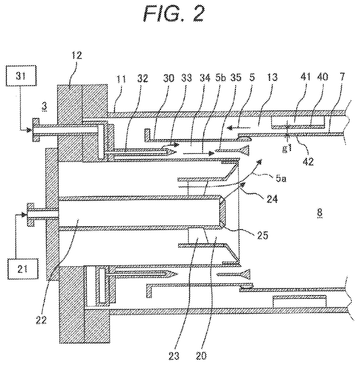
[0022]An explanation will be made conceptually with respect to the gas turbine power generation facility provided with a gas turbine combustor 3 (hereinafter referred to as a combustor) according to a first example.
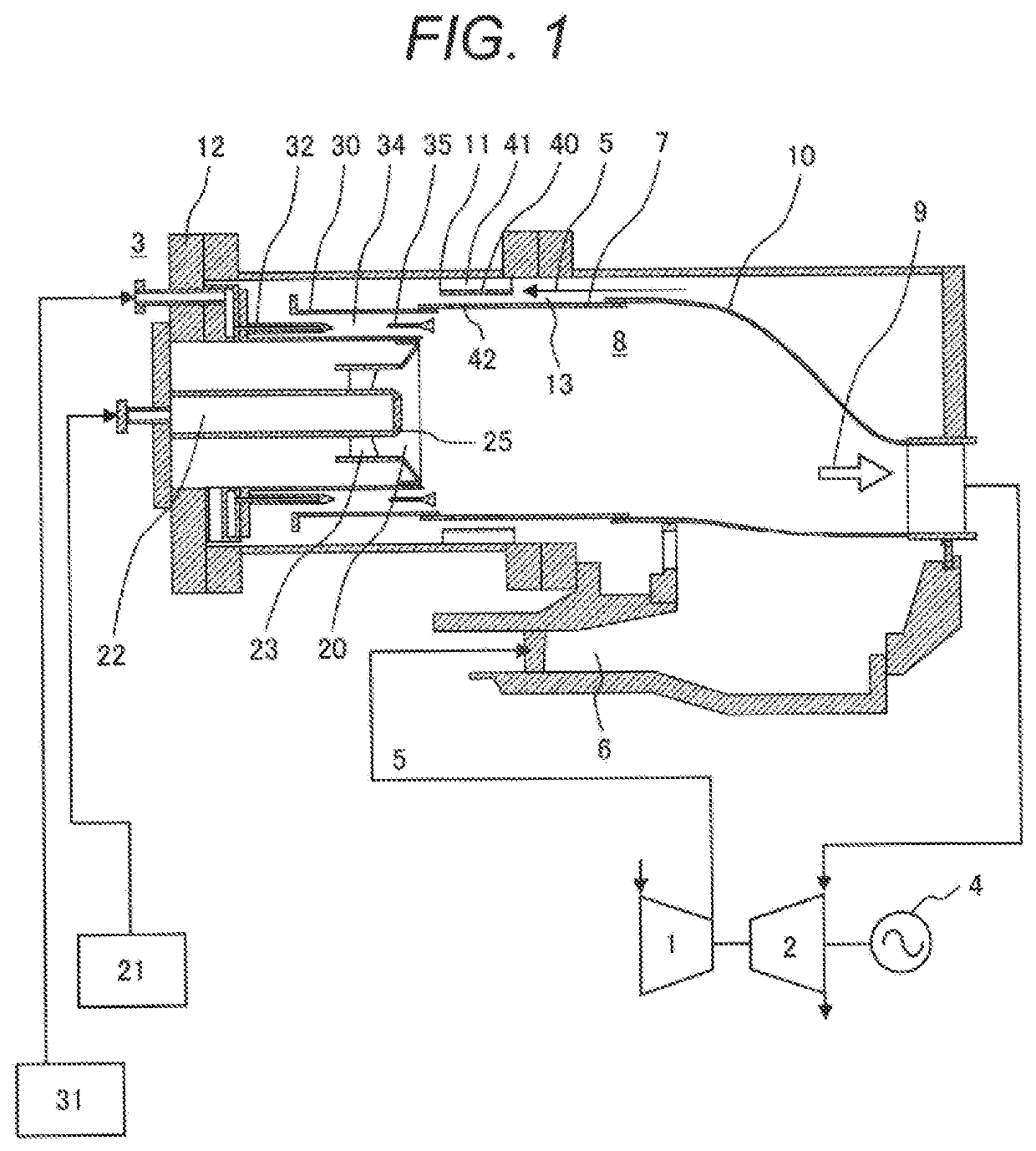
[0023]FIG. 1 conceptually illustrates the gas turbine power generation facility provided with the combustor 3 according to the first example.
[0024]The gas turbine power generation facility (gas turbine power plant) provided with the combustor 3 according to the first example includes a turbine 2, a compressor 1 connected to the turbine 2 for generating compressed air 5 for combustion, a plurality of gas turbine combustors 3, and a generator 4 connected to the turbine 2 for generating power in association with driving of the turbine 2. FIG. 1 shows one unit of the combustor 3 for convenience of explanation.
[0025]The compressed air 5 discharged from the compressor 1 is supplied to the combustor 3 via a compressed air passage 6. In a combustion chamber 8 formed inside a comb...
second example
[0052]A main part of the combustor 3 according to a second example will be briefly described.
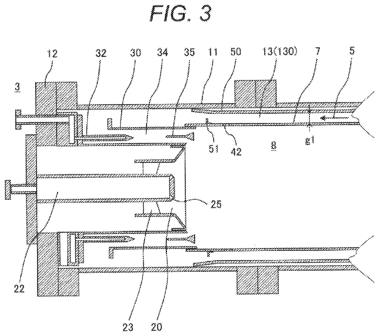
[0053]FIG. 3 is a schematic partially enlarged sectional view of the main part of the combustor 3 according to the second example.
[0054]The combustor 3 according to the second example is different from the combustor 3 according to the first example in the use of a flow sleeve 50 instead of the supports 41 and the vane 40.
[0055]The flow sleeve 50 is an annular member disposed in the annular passage 13 in substantially parallel to the combustion liner 7 in the radial direction of the annular passage 13 for narrowing its cross section area through which the compressed air 5 flows.
[0056]The flow sleeve 50 is disposed to expand toward the outer circumferential side downstream in the flow direction of the compressed air 5 flowing through the annular passage 13 (around the outer circumferential side of the flame stabilizer 35). The flow sleeve 50 is fixed to the inner circumferential side of the co...
third example
[0074]A main part of the combustor 3 according to a third example will be briefly described.
[0075]FIG. 4 is a schematic partially enlarged sectional view of the main part of the combustor 3 according to the third example.
[0076]The combustor 3 according to the third examples is different from the combustor 3 according to the first example in the state where the supports 41 and the vane 40 are disposed in the circumferential direction.
[0077]The combustor 3 according to the first example is configured to set the uniform gap g1 between the outer circumference (outer circumferential surface) of the combustion liner 7 and the inner circumference (inner circumferential surface) of the vane 40 in the circumferential direction. Meanwhile, the combustor 3 according to the third example is configured to set the non-uniform gap between the outer circumference (outer circumferential surface) of the combustion liner 7 and the inner circumference (circumferential surface) of the vane 40 in the cir...
PUM
 Abstract
Description
Claims
Application Information
 - R&D Engineer
- R&D Manager
- IP Professional
- Industry Leading Data Capabilities
- Powerful AI technology
- Patent DNA Extraction
Browse by: Latest US Patents, China's latest patents, Technical Efficacy Thesaurus, Application Domain, Technology Topic.
© 2024 PatSnap. All rights reserved.Legal|Privacy policy|Modern Slavery Act Transparency Statement|Sitemap