A birefringent interferometer for measuring photoluminescence properties of samples

a birefringent interferometer and sample technology, applied in the direction of radiation pyrometry, instruments, spectral investigation, etc., can solve the problems of known techniques for performing fluorescence (excitation) spectra measurement that have limitations in resolution, stability, light throughput, etc., and achieve high stability

Active Publication Date: 2021-04-29
POLITECNICO DI MILANO
View PDF0 Cites 0 Cited by
  • Summary
  • Abstract
  • Description
  • Claims
  • Application Information

AI Technical Summary

Benefits of technology

[0018]The Applicant has noticed that using an interferometer having a common-path geometry allows obtaining high stability on the relative delay

Problems solved by technology

The Applicant has noticed that the known techniques for performing measurements of fluores

Method used


Image

  • A birefringent interferometer for measuring photoluminescence properties of samples
  • A birefringent interferometer for measuring photoluminescence properties of samples
  • A birefringent interferometer for measuring photoluminescence properties of samples

Examples


Embodiment Construction

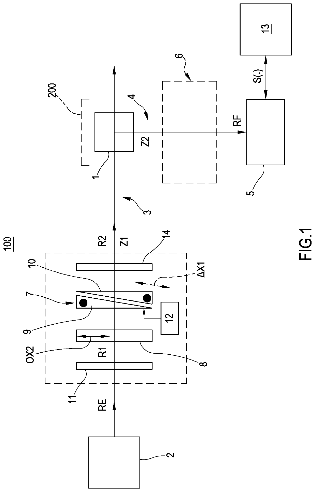
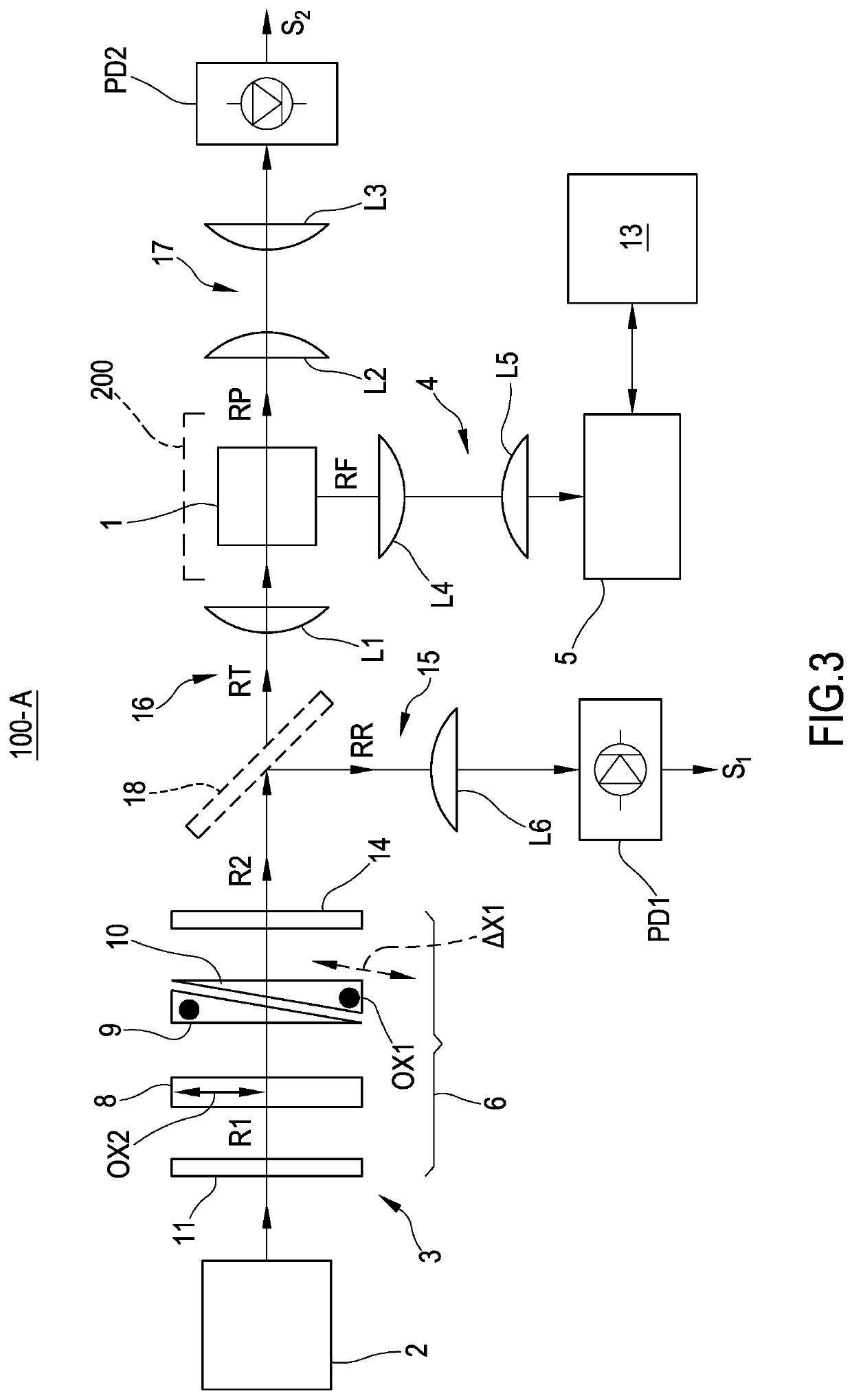
[0027]FIG. 1 shows an embodiment of measurement system 100 adapted to measure photoluminescence properties of samples. Particularly, measurement system 100 can be employed to measure fluorescence or phosphorescence properties of samples. The following description refers to the fluorescence measurements, but the same techniques also apply to phosphorescence properties of samples, as it will be clear to the skilled person.

[0028]Sample 1 is suitably mounted on a support or holder 200 (schematically represented in the drawings).

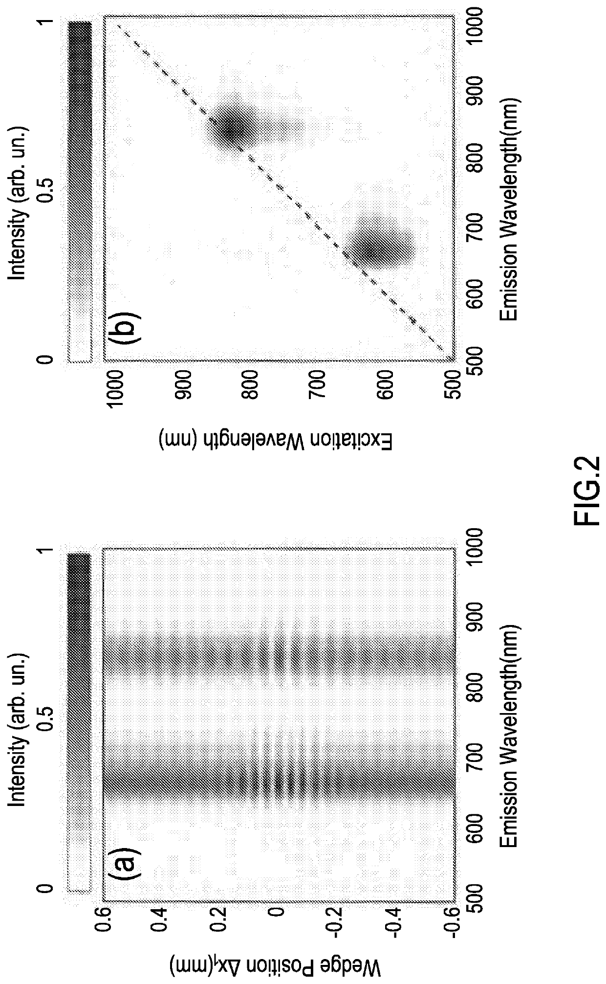
[0029]Measurement system 100 can be configured to measure at least one of the following quantities: the Excitation-Emission-Matrix (EEM), fluorescence emission spectra and fluorescence excitation spectra of samples. The above-indicated quantities can be measured over a broad bandwidth in any spectral region, including the UV region, the visible region, the near-infrared region and the infrared regions. The above-indicated quantities can be also measured using pho...


PUM


Abstract

A measurement system of photoluminescence properties of a sample, comprises a radiation source module configured to generate a first radiation, an excitation optical path coupled to the radiation source module, a support structured to support a sample to be optically coupled to excitation optical path and adapted to provide a photoluminescence radiation, and collection path coupled to the sample and configured to propagate the photoluminescence radiation. The system also includes an analysis device configured to receive the photoluminescence radiation and provide data/information on photoluminescence properties of sample. At least one path between the excitation path and the collection path comprises a respective adjustable birefringent common-path interferometer module configured to produce first and second radiations adapted to interfere with each other.

Description

STATEMENT OF FEDERAL FUNDING[0001]The project leading to this patent application has received funding from the European Research Council (ERC) under the European Union's Horizon 2020 research and innovation program (grant agreements No 648615 and 754802).TECHNICAL FIELD[0002]The present invention relates to techniques for measuring photoluminescence properties of samples.DESCRIPTION OF THE RELATED ART[0003]Photoluminescence is the spontaneous emission of light from a material following optical excitation. Photoluminescence includes, as an example, fluorescence and phosphorescence.[0004]For phosphorescence, the absorbed photons excite electrons from the ground state to an excited state. After the excitation, these electrons undergo intersystem crossing where they enter a state with altered spin multiplicity, usually a triplet state. Once energy from this absorbed photon is partially transferred in this triplet state, the electronic transitions back to the lower singlet energy states ...

Claims


Application Information

Patent Timeline
IPC IPC(8): G01J3/45G01J3/02G01J3/28G02B5/30
CPCG01J3/45G01J3/0224G01J3/0208G02B5/3083G01J3/0237G01J3/2823G01J3/0205
Inventor POLLI, DARIOCERULLO, GIULIOPREDA, FABRIZIOPERRI, ANTONIOHAUER, JÜRGEN
Owner POLITECNICO DI MILANO
Why Eureka
Try Eureka