
Electronic device package and method for manufacturing the same

Pending Publication Date: 2021-04-29
ADVANCED SEMICON ENG INC
View PDF3 Cites 2 Cited by
  • Summary
  • Abstract
  • Description
  • Claims
  • Application Information

AI Technical Summary

Benefits of technology

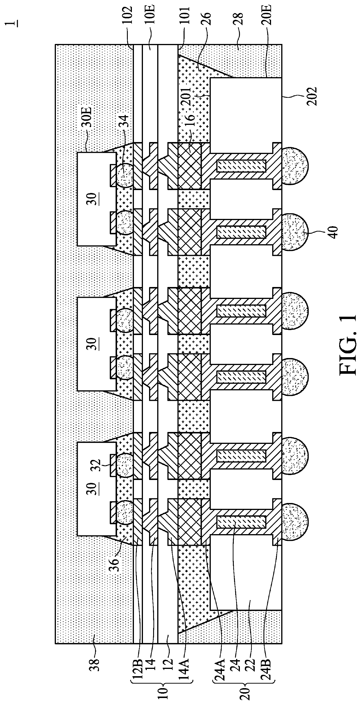
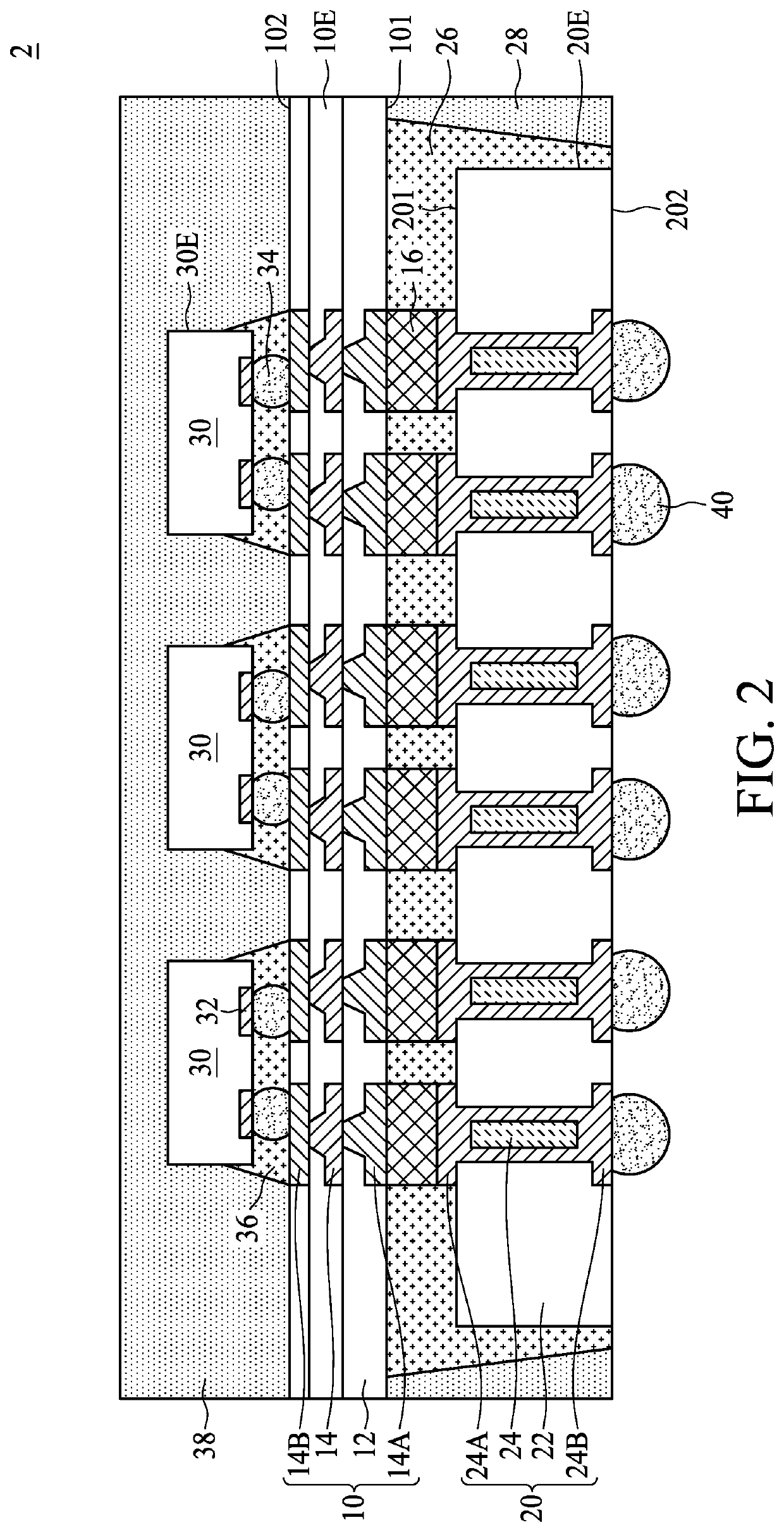
The patent text describes different ways to create electronic device packages. One way includes using a redistribution layer (RDL) with a higher circuit density than a conductive substrate, where the RDL is electrically connected to the substrate. Another way includes using a fan-out circuit layer with a larger area than both the substrate and the semiconductor die, which are connected to it. The method described in the patent text involves dividing a mother substrate into multiple substrates and mounting them on a redistribution substrate before further dividing the redistribution substrate into RDLs. These different methods can improve the efficiency and performance of electronic device packaging.

Problems solved by technology

The underfill, however, may creep up edges of the electronic component, making it difficult to remove the carrier for temporarily supporting the electronic component.

Method used


Image

  • Electronic device package and method for manufacturing the same
  • Electronic device package and method for manufacturing the same
  • Electronic device package and method for manufacturing the same

Examples


Embodiment Construction

[0010]The following disclosure provides for many different embodiments, or examples, for implementing different features of the provided subject matter. Specific examples of components and arrangements are described below to explain certain aspects of the present disclosure. These are, of course, merely examples and are not intended to be limiting. For example, the formation of a first feature over or on a second feature in the description that follows may include embodiments in which the first and second features are formed or disposed in direct contact, and may also include embodiments in which additional features are formed or disposed between the first and second features, such that the first and second features are not in direct contact. In addition, the present disclosure may repeat reference numerals and / or letters in the various examples. This repetition is for the purpose of simplicity and clarity and does not in itself dictate a relationship between the various embodiments...


PUM


Abstract

An electronic device package includes a redistribution layer and a conductive substrate. The RDL includes a first surface. The conductive substrate is disposed on the first surface and electrically connected to the RDL. A circuit density of the RDL is higher than a circuit density of the conductive substrate, and an edge of the RDL laterally protrudes out from a respective edge of the conductive substrate.

Description

BACKGROUND1. Technical Field[0001]The present disclosure relates to an electronic device package including a stack of electronic components.2. Description of the Related Art[0002]A stacking electronic device package includes two or more electronic components stacked on each other. The stacked electronic components are electrically connected to each other through conductive structures such as solder bumps, and an underfill is normally formed to ensure the joint between the stacked electronic components. The underfill, however, may creep up edges of the electronic component, making it difficult to remove the carrier for temporarily supporting the electronic component.SUMMARY[0003]In some embodiments, an electronic device package includes a redistribution layer and a conductive substrate. The RDL includes a first surface. The conductive substrate is disposed on the first surface and electrically connected to the RDL. A circuit density of the RDL is higher than a circuit density of the ...

Claims


Application Information

Patent Timeline
IPC IPC(8): H01L23/00H01L23/31
CPCH01L24/05H01L2224/02371H01L2224/02379H01L23/3135H01L21/4846H01L23/3128H01L23/49838H01L21/6835H01L2221/68345H01L23/5385H01L23/145H01L23/49816H01L23/5383H01L2224/32225H01L2224/16225H01L2924/181H01L2924/15311H01L2224/73204H01L2224/13101H01L2224/13147H01L2224/2919H01L2224/8385H01L2224/81801H01L24/13H01L24/29H01L24/32H01L24/16H01L24/73H01L24/81H01L24/83H01L24/97H01L2924/00012H01L2924/014H01L2924/00014H01L2924/0665H01L23/5384H01L21/486H01L23/5386H01L21/561H01L21/568H01L21/563H01L25/0753
Inventor HUANG, WEN HUNG
Owner ADVANCED SEMICON ENG INC
Learn More