Secondary battery protection circuit and secondary battery anomaly detection system
- Summary
- Abstract
- Description
- Claims
- Application Information
AI Technical Summary
Benefits of technology
Problems solved by technology
Method used
Image


Examples
embodiment 1
[0066]FIG. 1(A) shows an example of a block diagram of a protection circuit 100 which performs anomaly detection on a secondary battery 101.
[0067]As illustrated in FIG. 1(A), the protection circuit 100 for the secondary battery 101 includes at least a comparison circuit 102, a first memory 103, a second memory 104, a power-off switch 105, and a control circuit.
[0068]Although the secondary battery 101 and the protection circuit 100 are separately illustrated in FIG. 1(A), a terminal of the secondary battery 101 and a terminal of the protection circuit 100 mounted on a circuit board are each fixed by solder connection as a secondary battery module, in some cases.
[0069]A lithium-ion secondary battery is used as the secondary battery 101. In a lithium-ion secondary battery, deterioration is promoted if charging or discharging is performed excessively. Accordingly, in order to prevent overcharging and overdischarging, the condition at charging and discharging is controlled with a control...
embodiment 2
[0093]In this embodiment, an example of flow which is different from that in Embodiment 1 is described. FIG. 5 shows an example of a flow for the case where anomaly detection is performed on a mobile device equipped with a secondary battery a plurality of times in one charging operation.
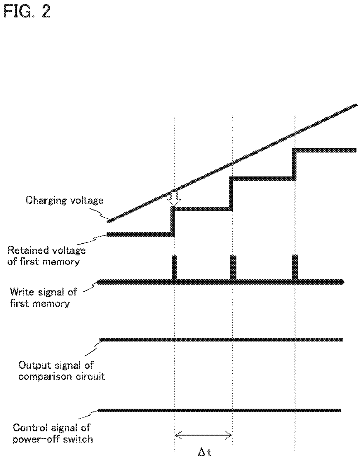
[0094]First, voltage value data of a secondary battery is acquired with a voltage value acquisition means such as a voltage monitor (S1). Then, the offset voltage data of the secondary battery is written to the first memory circuit every sampling period Δt (S2).
[0095]Voltage values measured at the present time and a different time are compared (comparison step: S3). In the case where the comparison result indicates that the difference between the two input voltages is small, the above-described data acquisition and comparison repeat. When charging continues without any detection of an anomaly and reaches full charge (S7), charging stops (S8).
[0096]In the case where the difference between the two inpu...
embodiment 3
[0101]In this embodiment, an example of using a plurality of transistors in the first memory 103 is described.
[0102]In this embodiment, data of the offset voltage value of a secondary battery is created by using two transistors in the first memory 103 as shown in FIG. 6(A). With the use of two transistors, the offset value can be adjusted. The offset refers to a voltage that is slightly output even though the input signal is 0 V.
[0103]Note that in FIG. 6(A), the same portions as those in FIG. 1(A) are denoted by the same reference numerals.
[0104]Moreover, one capacitor may be added to form the first memory 103 shown in FIG. 6(B). The data of the offset voltage value of the secondary battery can be created by capacitive coupling with the capacitor.
[0105]Note that in FIG. 6(B), the same portions as those in FIG. 1(A) are denoted by the same reference numerals.
[0106]With the structure of the first memory 103 shown in FIG. 6(A) or FIG. 6(B), the offset amount can be adjusted and the vol...
PUM
 Abstract
Description
Claims
Application Information
 - R&D
- Intellectual Property
- Life Sciences
- Materials
- Tech Scout
- Unparalleled Data Quality
- Higher Quality Content
- 60% Fewer Hallucinations
Browse by: Latest US Patents, China's latest patents, Technical Efficacy Thesaurus, Application Domain, Technology Topic, Popular Technical Reports.
© 2025 PatSnap. All rights reserved.Legal|Privacy policy|Modern Slavery Act Transparency Statement|Sitemap|About US| Contact US: help@patsnap.com