
Endoscopic cryoablation catheter

a cryoablation catheter and endoscope technology, applied in the field of medical devices, can solve the problems of inability to resection tumors, rfa risks thermal injury to important structures such as the bile duct, the duodenum, and the closure of vessels, and achieve the effect of reducing the overall cost, reducing the risk of complications, and reducing the procedure tim

Pending Publication Date: 2021-05-06
CPSI HLDG
View PDF0 Cites 5 Cited by
  • Summary
  • Abstract
  • Description
  • Claims
  • Application Information

AI Technical Summary

Benefits of technology

The invention is a cryoablation device integrated with an endoscope that can quickly and effectively treat pancreatic cancer and other gastrointestinal cancers or unwanted tissues. The device has a flexible and steerable probe that can be placed through the stomach wall and into the pancreas, making it a minimally invasive option compared to laparoscopy or surgery. The device uses cryogenic temperatures to target and destroy cancer cells without damaging the surrounding tissue. The method involves inserting the probe, delivering cryo hopeful treatment, allowing the tissue to thaw or heat, and removing the probe. The endoscopic approach reduces procedure time, costs, and risks, offering a more effective therapeutic option for pancreatic cancer patients.

Problems solved by technology

In about 20% of patients with no metastases, tumor resection is not feasible because of vascular invasion, poor general health, or lacking surgical techniques.
As utilized in the treatment of pancreatic cancer, RFA risks thermal injury to important structures such as the bile duct, the duodenum, and vessels close to the pancreas.
A major limitation with RFA is difficulty in assessing the ablated zone by ultrasound, magnetic resonance imaging (MRI) or computed tomography (CT) scan.
The poorly perfused pancreatic area also makes it difficult to visualize.
Further, studies have demonstrated that radiologic follow-up after ablation could not distinguish inflammatory reactions of the tumor tissue from tumor growth or necrosis within the first four weeks.
Yet, broad based clinical utilization has been limited by commercial devices that do not provide adequate cooling power to effectively treat the cancerous tissue.
The invasive nature of surgical (open or laparoscopic) access to the target also remains an ongoing issue along with technological limitations.
In addition, current cryoprobes as used in an endoscopic procedure can cause damage to the endoscope due to freezing of the catheter shaft to the inside of the endoscope.
This can interfere with the ultrasound imaging and readjusting or removing the cryoprobe from the tissue or endoscope in a timely manner.
Prolonged procedures also can cause freezing of the endoscope to surrounding tissue resulting in damage to non-target tissues such as the esophagus, stomach wall, colon, intestine, rectum or other structure.
Issues related to laparoscopic ablation techniques, however, make imaging difficult.
For example, anatomical location of the pancreas makes it difficult to visualize and access without damaging other tissues.

Method used


Image

  • Endoscopic cryoablation catheter
  • Endoscopic cryoablation catheter
  • Endoscopic cryoablation catheter

Examples


Embodiment Construction

[0035]Disclosed herein is an endoscopic cryoablation apparatus for the ablation of undesirable tissue. A method of utilizing the endoscopic cryoablation apparatus to treat pancreatic cancer, gastrointestinal cancer, or other such tissue is also incorporated.

[0036]In describing the invention, reference will be made to various embodiments, examples of which are illustrated in the accompanying drawings. Wherever possible, the same or like reference numbers will be used throughout the drawings to refer to the same or like parts.

[0037]A. Cryoablation Catheters Having a Sheath

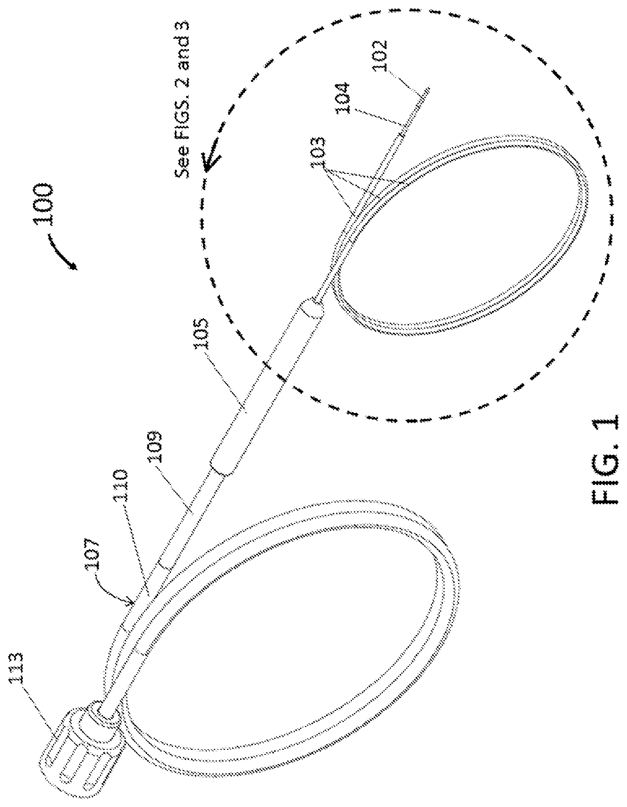
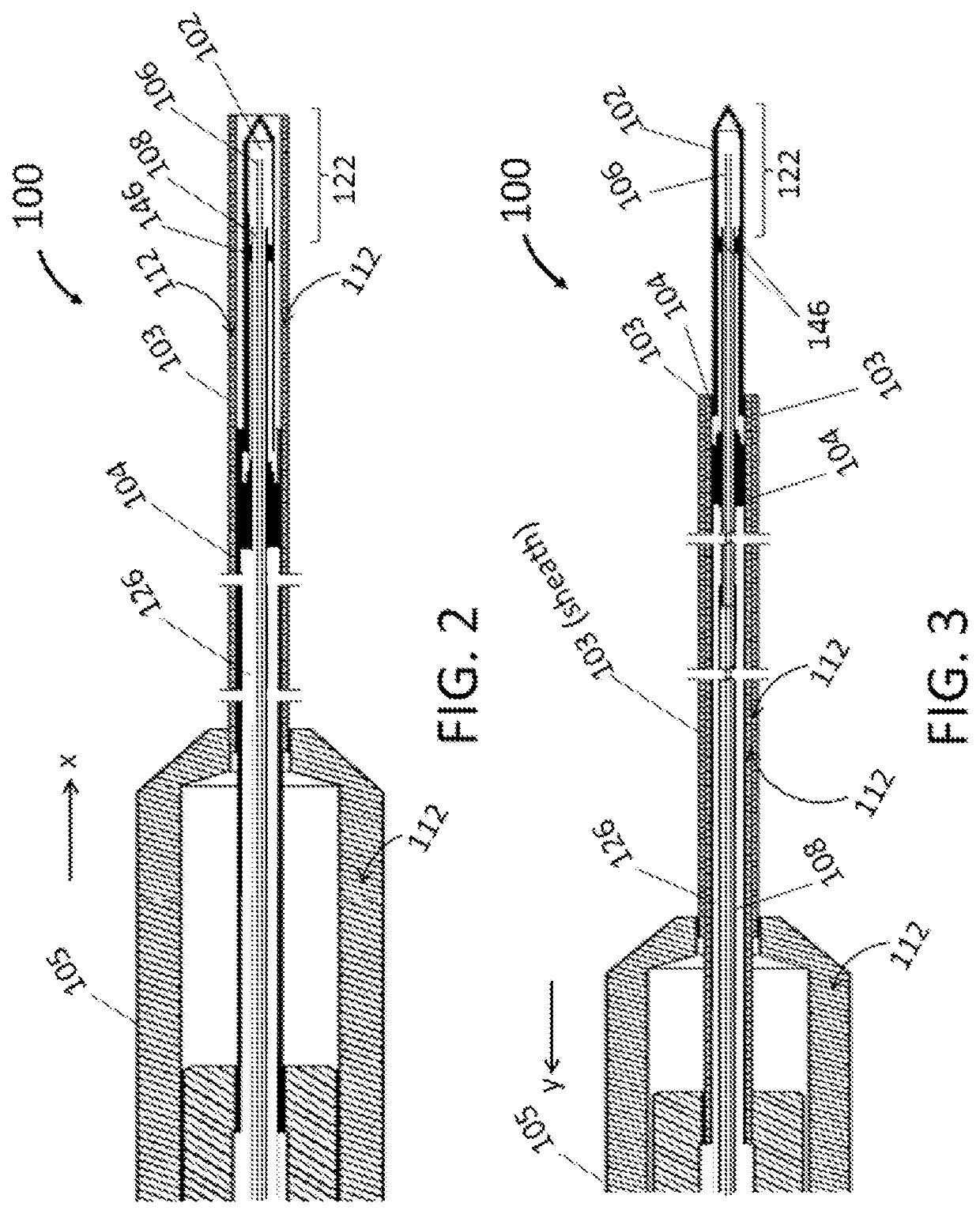
[0038]As illustrated in FIG. 1, the endoscopic cryoablation apparatus 100 comprises a cryoprobe tip 102 with an ablation zone 122 and integrated with a catheter shaft 104 such that a moveable sheath 103 covers and exposes the cryoprobe tip 102 by way of a controllable handle 105. As depicted, an umbilical 110 has an outer wall 107 and attaches to a connector 113 at a proximal end of the endoscopic cryoablation appara...


PUM


Abstract

A cryoablation device is provide herein which, in an embodiment, includes a catheter shaft and a cryogen return line disposed within the catheter shaft. A cryogen supply line is disposed within the cryogen return line, such that the cryogen supply line, the cryogen return line, and the catheter shaft are all substantially coaxial. A needle tip probe is disposed at a distal end of the cryogen return line and the cryogen supply line extends in a distal direction beyond a distal end of the cryogen return line and into the needle tip probe. An insulating tube is disposed circumferentially around the cryogen return line and within the catheter shaft. An insulating lumen is circumferentially disposed around the return line, between an inner diameter of the catheter shaft and an outer diameter of the insulating tube. A position of the insulating tube is fixed relative to the catheter shaft. A position of the needle tip probe and the cryogen return line is axially and rotationally movable with respect to the insulating tube and the catheter shaft.

Description

CROSS REFERENCE TO RELATED APPLICATIONS[0001]The present application is a continuation-in-part of co-pending U.S. application Ser. No. 15 / 881,441, filed Jan. 26, 2018, which was a continuation-in-part of U.S. application Ser. No. 13 / 937,658, filed Jul. 9, 2013 and issued as U.S. Pat. No. 9,877,767 on Jan. 30, 2018, which claims the benefit of U.S. Application No. 61 / 783,488, filed Mar. 14, 2013. Each of the foregoing US patent applications is incorporated by reference as though fully set forth herein.FIELD OF THE INVENTION[0002]The present invention relates generally to medical devices, and, in particular, to a surgical catheter for cryoablation.BACKGROUND OF THE INVENTION[0003]Pancreatic cancer is one of the major causes of cancer death in Western countries. In 2010, an estimated 43,140 new cases of pancreatic cancer were diagnosed in the United States with an expected five year survival rate of less than about 10%. In about 20% of patients with no metastases, tumor resection is no...

Claims


Application Information

Patent Timeline
Patent Type & Authority Applications(United States)
IPC IPC(8): A61B18/02A61B18/14
CPCA61B18/02A61B18/1492A61B2018/00577A61B2018/0212A61B2018/0262A61B2018/00041A61B2018/00101A61B2018/0293A61B2090/3784A61B2218/002A61B2218/007
Inventor BAUST, JOHN M.
Owner CPSI HLDG
Learn More