Check patentability & draft patents in minutes with Patsnap Eureka AI!

Method and apparatus for emissions mitigation on a hybrid vehicle

a hybrid vehicle and emission mitigation technology, applied in the direction of battery/fuel cell control arrangement, electric control, engine starters, etc., can solve the problems of increasing weight, reducing fuel throughput, and unable to reduce or eliminate certain particulates through efficient catalyst operation, so as to reduce the amount of pollutant generated and the fuel throughput

Active Publication Date: 2021-05-06
GM GLOBAL TECH OPERATIONS LLC
View PDF0 Cites 0 Cited by
  • Summary
  • Abstract
  • Description
  • Claims
  • Application Information

AI Technical Summary

Benefits of technology

The engine method described in this patent aims to minimize fuel consumption and pollutant emissions during the initial phase of engine operation. This is achieved by placing restrictions on the engine power output to avoid excessive fuel throughput and pollutant production.

Problems solved by technology

The battery is at a peak capacity when new and may degrade with use and age.
When battery power is insufficient to provide motive power, engine operation may be necessary.
Cold start engine emissions reduction strategies exist for these pollutants, however certain particulates cannot be reduced or eliminated by efficient catalyst operation.
Particulate filters are therefore utilized for soot removal, however particulate filters require space, add weight and incur additional design and installation cost.
In a partial hybrid electric vehicle (PHEV) application this may cause excessive emissions because the PHEV and the battery cannot operate the same as at the beginning of battery life.
This may result in failure of in-use government emissions cycle testing.
In addition, output torque must be maintained to drive the cycle, therefore the options of solely limiting PHEV operation to engine operation or allowing an over-depletion of the HV battery to obtain output torque are not acceptable solutions to loss of HV battery power.
It has been found that limiting a battery SOC range to provide more charge sustaining energy may also prevent meeting the electric vehicle (EV) range requirements.

Method used


Image

  • Method and apparatus for emissions mitigation on a hybrid vehicle
  • Method and apparatus for emissions mitigation on a hybrid vehicle

Examples


Embodiment Construction

[0031]The following description is merely exemplary in nature and is not intended to limit the present disclosure, application, or uses.

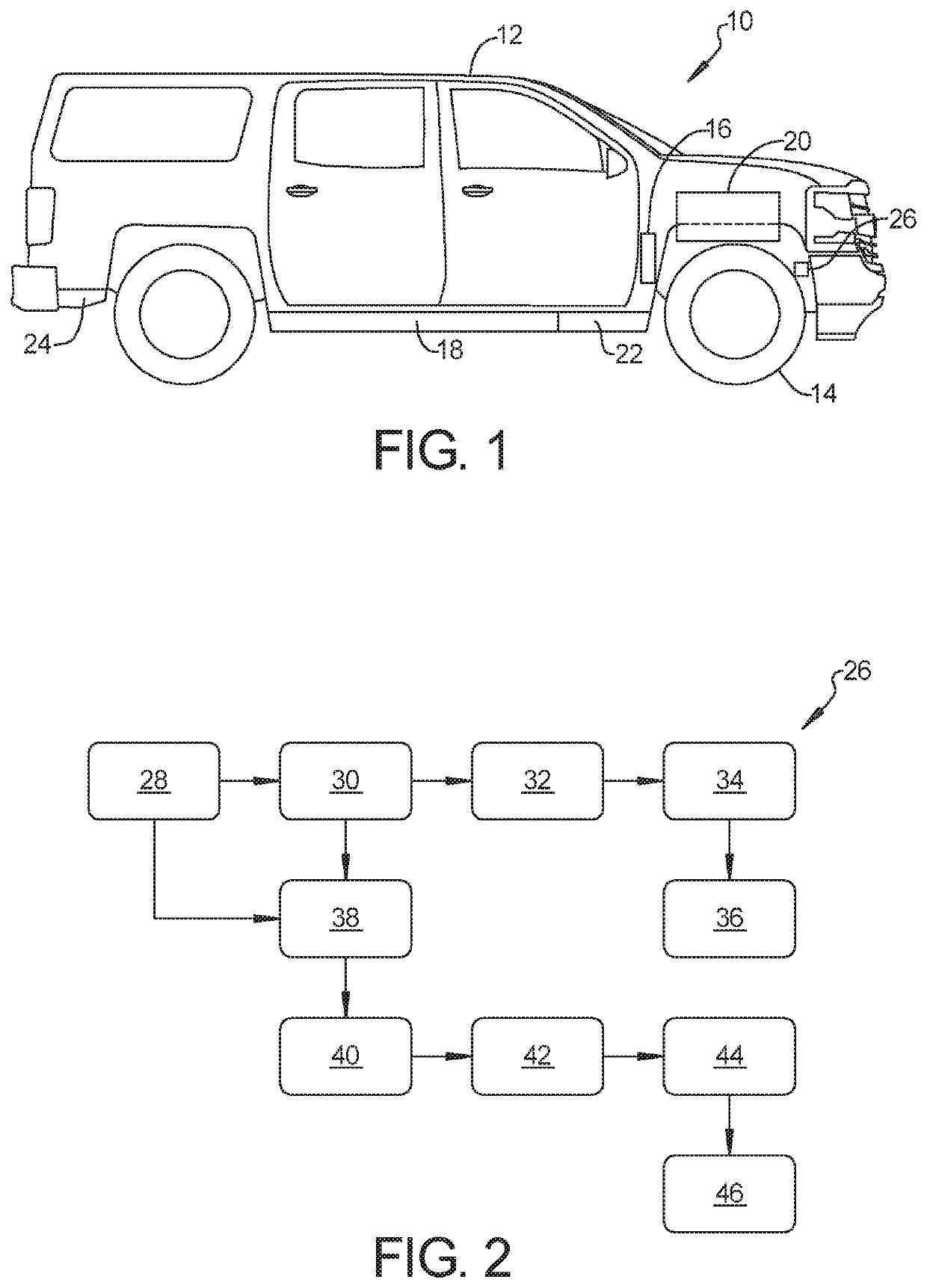
[0032]Referring to FIG. 1, a system for emissions mitigation for a hybrid automobile vehicle 10 includes an apparatus for emissions mitigation on a hybrid vehicle 12. The hybrid vehicle (HV) 12 includes at least one driven wheel 14 which is rotated by operation of an electric motor 16. Motive power for operation of the electric motor 16 may be provided by a battery pack 18 having multiple battery cells and may be supplemented with power from an engine 20 such as a gasoline engine or a diesel engine. According to several aspects, power may also be distributed between the battery pack 18 and the engine 20 using a transmission 22 providing multiple gear ratios.

[0033]To maximize operating economy and minimize fuel consumption it is anticipated to operate the HV 12 using power from the battery pack 18 to a maximum extent. In addition, operation of the en...


PUM


Abstract

A system for emissions mitigation for a hybrid automobile vehicle includes an automobile vehicle provided with motive power from: a battery pack; an engine; and a controller in communication with the battery pack and the engine. A threshold battery pack state-of-charge (SOC) is predetermined. A minimum battery pack SOC is less than the threshold battery pack SOC. An engine-on charge depletion (EOCD) command is issued by the controller to start the engine in an engine-catalyst light-off operation condition when the vehicle is operating using power from the battery pack and when the threshold battery pack state-of-charge (SOC) is reached to mitigate against exceeding vehicle emissions standards.

Description

INTRODUCTION[0001]The present disclosure relates to hybrid vehicle battery and emissions control systems.[0002]Hybrid vehicles (HVs) derive at least a portion of motive power from a battery provided as a battery pack having multiple individual battery cells. The battery is at a peak capacity when new and may degrade with use and age. HVs may operate solely on battery power, solely on engine power, or using a combination of battery and engine power. When battery power is insufficient to provide motive power, engine operation may be necessary. Engine operation generates multiple pollutants, one of which are particulate emissions, many of which are regulated by government standards. Several pollutants are commonly controlled using a catalyst. Cold start engine emissions reduction strategies exist for these pollutants, however certain particulates cannot be reduced or eliminated by efficient catalyst operation. Particulate filters are therefore utilized for soot removal, however particu...

Claims


Application Information

Patent Timeline
IPC IPC(8): B60W20/13B60L50/60B60L58/13F02N11/00F02D41/02B60W10/06
CPCB60W20/13B60L50/66B60L58/13F02N11/00F02D41/0255B60W10/08F02N2200/023F02D2200/021F02D2200/101F02D2200/503B60W10/06B60W20/16B60W40/00B60W2510/244B60W2710/06B60L58/25B60L2240/545B60L2240/441B60L50/61Y02T10/62Y02T10/70Y02T90/16F02D29/02F02N11/0825F02N2200/061B60W30/194B60W2710/0644B60W2555/20B60W2510/246B60W2710/0688B60W2710/065Y02T10/12Y02T10/40
Inventor PIPER, ERIC D.ZETTEL, ANDREW H.HEAP, ANTHONY H.
Owner GM GLOBAL TECH OPERATIONS LLC
Features
  • R&D
  • Intellectual Property
  • Life Sciences
  • Materials
  • Tech Scout
  • Unparalleled Data Quality
  • Higher Quality Content
  • 60% Fewer Hallucinations
Learn More