Lidar sensor

a technology of lidar sensor and sensor body, which is applied in the field of lidar sensor, can solve the problems of reducing service life, complicated rotor design, and increasing costs, and achieves compact design, compact design, and reduced size of lidar sensor.

Pending Publication Date: 2021-05-27
ROBERT BOSCH GMBH
View PDF0 Cites 4 Cited by
  • Summary
  • Abstract
  • Description
  • Claims
  • Application Information

AI Technical Summary

Benefits of technology

[0028]Furthermore, it is advantageous when a range of the LIDAR sensor is variable over its visual field, in particular that the range of the LIDAR sensor in a lateral area of the visual field is smaller than in a central area of the visual field. The lateral area is in particular a lateral area in the horizontal direction of the visual field. The LIDAR sensor may thus have a particularly compact design.

Problems solved by technology

However, these systems have several disadvantages for series production in vehicles.
This results in increased costs and reduces the service life.
In addition, the requirements for stability of the LIDAR sensor due to the vibrations caused by the vehicle result in a complicated rotor design.
However, combined with the high power consumption, the demand on the cooling by the vehicle is very high.
In addition, the LIDAR sensor has a very large design.
This makes integration into a vehicle difficult.
Thus far, a LIDAR sensor including a rotating mirror has not been suitable for a design with a constant range, since in the technology up to now, the optical transmission area and reception area must be strictly separated due to the fact that the receiver (or the amplifier electronics system) has a long recovery time, resulting in transmission-reception coupling in the sensor for a large dead range in the near field of the sensor.
The situation is thus avoided that, due to a large vertical visual field, a required installation space for the transmission area and reception area becomes unnecessarily large, since a large amount of space has been necessary thus far for separating the transmission area and the reception area.

Method used


Image

  • Lidar sensor
  • Lidar sensor
  • Lidar sensor

Examples


Embodiment Construction

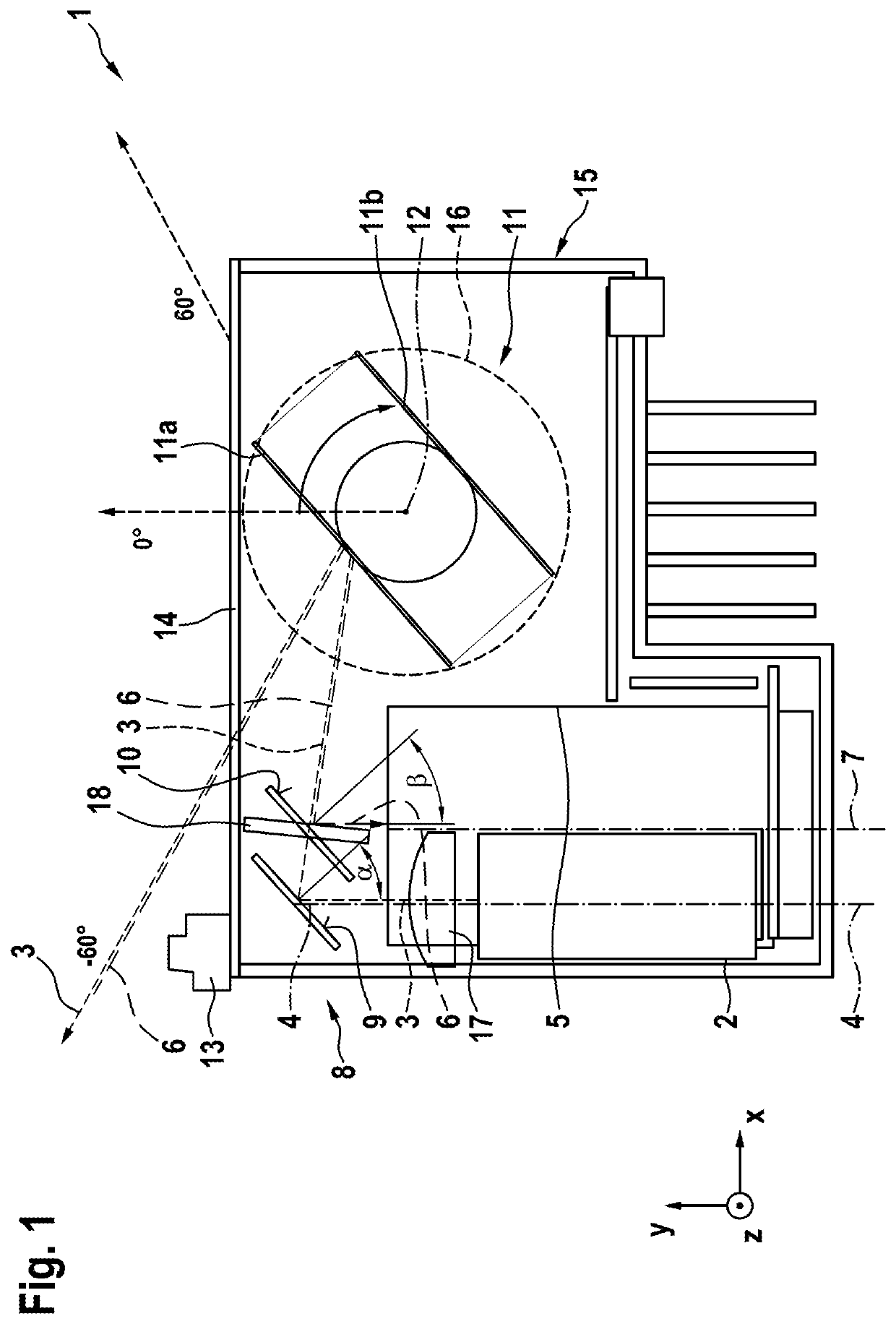
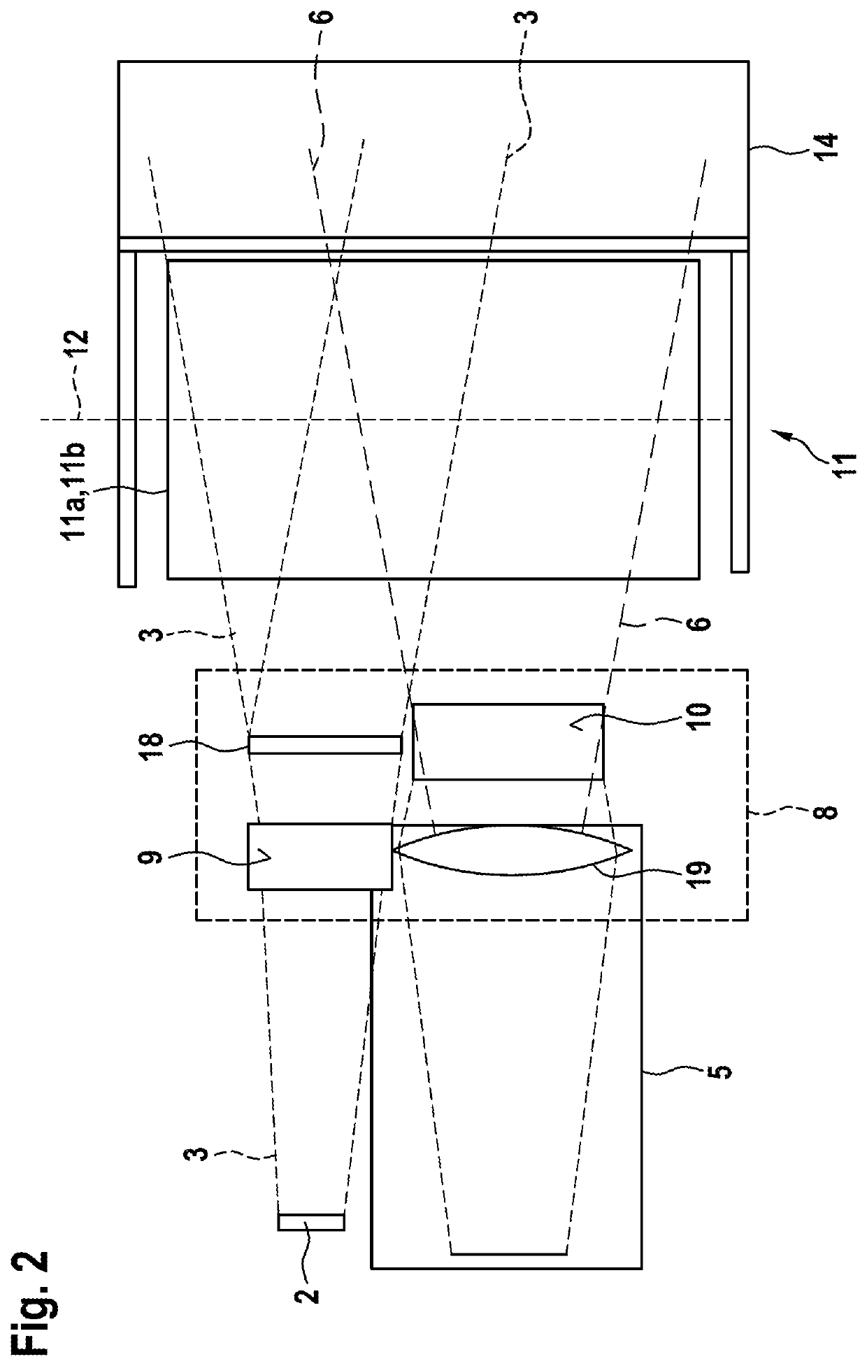
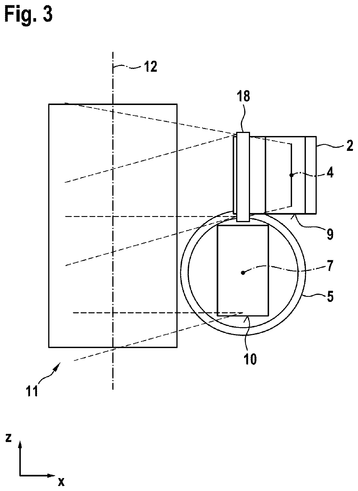
[0034]FIG. 1 shows a LIDAR sensor 1 according to one specific embodiment of the present invention. LIDAR sensor 1 is illustrated from a top view that depicts an XY plane. LIDAR sensor 1 includes an optical transmitting unit 2, an optical receiving unit 5, a deflection optical system 8, and a scanning unit 11. Optical transmitting unit 2, optical receiving unit 5, deflection optical system 8, and scanning unit 11 are situated at a housing 15 of the LIDAR sensor. One side of housing 15 includes a viewing window 14.

[0035]Optical transmitting unit 2 is configured to emit a scanning beam 3 in the direction of an optical axis 4 of optical transmitting unit 2. In this specific embodiment, optical transmitting unit 2 is a line laser, a laser line of the line laser being oriented in parallel to a rotational axis 12 of scanning unit 11 and emitted as a scanning beam 3. This means that the laser line generated by optical transmitting unit 2 in the illustration of LIDAR sensor 1 shown in FIG. 1...


PUM


Abstract

A LIDAR sensor including an optical transmitting unit configured to emit a scanning beam in the direction of an optical axis of the optical transmitting unit, an optical receiving unit configured to receive the reflected scanning beam after the scanning beam has been reflected in the surroundings, a deflection optical system including a first mirror surface and a second mirror surface, the optical axis of the optical transmitting unit being directed onto the first mirror surface, and the optical axis of the optical receiving unit being directed onto the second mirror surface, the optical transmitting unit and the optical receiving unit being situated in an optical path of the LIDAR sensor on a shared first side of the deflection optical system, and a scanning unit situated in the optical path of the LIDAR sensor on a second side of the deflection optical system and configured to guide the scanning beam.

Description

CROSS REFERENCE[0001]The present application claims the benefit under 35 U.S.C. § 119 of German Patent Application No. DE 102019218005.1 filed on Nov. 22, 2019, which is expressly incorporated herein by reference in its entirety.FIELD[0002]The present invention relates to a LIDAR sensor including an optical transmitting unit, an optical receiving unit, and a scanning unit.BACKGROUND INFORMATION[0003]In the automotive field, thus far there have been LIDAR sensors that are designed primarily for driver assistance systems. These LIDAR sensors often have a field of view that is forward-facing. Although they have a large horizontal visual field, the range decreases greatly with increasing distance from the center axis.[0004]When LIDAR sensors are used for autonomous driving, systems including an active rotor are used in test vehicles. These systems naturally have a very large horizontal opening angle and a constant range across this opening angle. However, these systems have several disa...

Claims


Application Information

Patent Timeline
Patent Type & Authority Applications(United States)
IPC IPC(8): G01S7/481B08B1/00
CPCG01S7/4817G01S7/4814G01S17/931B08B1/006G01S7/4813G01S7/4802G01S7/481G01S7/497G01S17/02G01S2007/4977B08B1/005G01S17/42G01S7/4812G01S7/4972G01S2007/4975
Inventor NEUSTADT, ALF
Owner ROBERT BOSCH GMBH
Why Eureka
Try Eureka