Eureka AIR delivers breakthrough ideas for toughest innovation challenges, trusted by R&D personnel around the world.

Equipment carrying system

a technology of equipment and carrying systems, applied in fire rescue, respiratory apparatus, respiratory device storage, etc., can solve the problems of relocating the bag, affecting and the bag lying on the floor, so as to facilitate organization and tidiness, and eliminate loose hoses. , the effect of increasing the effectiveness of the rescue team

Inactive Publication Date: 2021-07-01
COVINGTON RON
View PDF0 Cites 0 Cited by
  • Summary
  • Abstract
  • Description
  • Claims
  • Application Information

AI Technical Summary

Benefits of technology

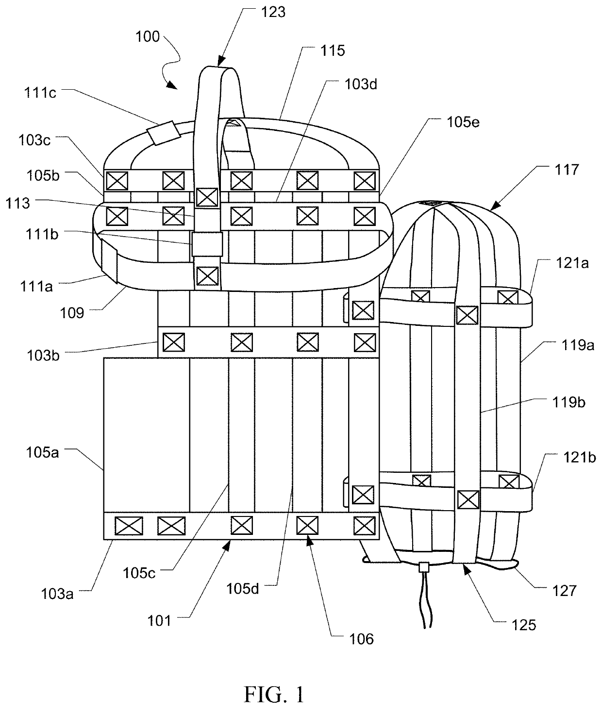
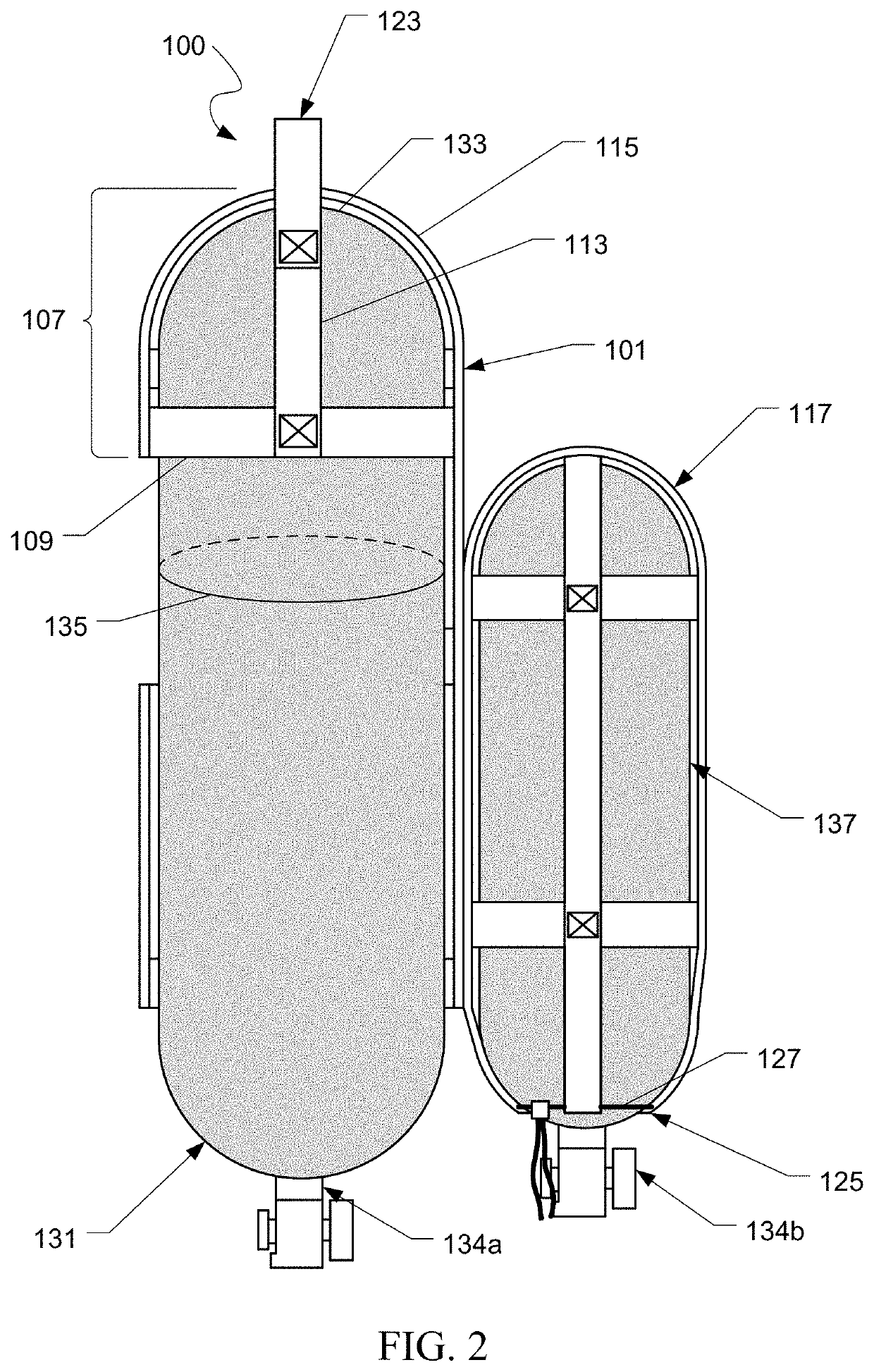
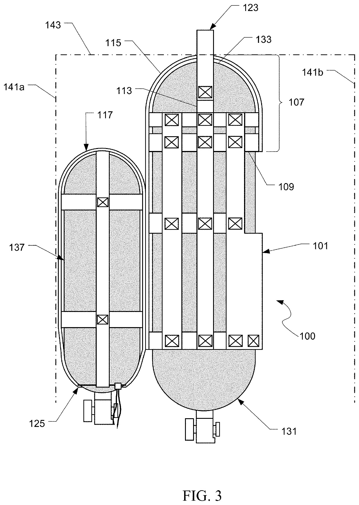
The current equipment carrying system allows a rescue team member to carry in rescue equipment without losing performance. It is designed to be carried by a member of the rescue team and is small in size. Reels located on the wearer's sides help to organize and tidiness. This system increases the effectiveness of the rescue team by allowing both members to carry in equipment.

Problems solved by technology

The weight and size of the RIT bag presents a challenge in transporting the bag in a hazardous environment that has fallen and / or burning debris, and where visibility is almost zero.
Another issue arises where the team must use a ladder to reach other floors.
For more challenging situations that require the carrier to use both hands, the carrier must let go of the bag; however, in a smoke filled environment, this can create a problem in relocating the bag again due to low visibility from the smoke.
A further disadvantage of the RIT bag is that the bag lies on the floor during use and has a number of compartments for holding equipment.
As the items are removed, especially in low visibility environments, it gets difficult to see where those items are located.
While wearing gloves, this is extremely difficult to do.
It is not uncommon for hoses from the RIT bag to be a tripping hazard or for items to be lost.

Method used


Image

  • Equipment carrying system
  • Equipment carrying system
  • Equipment carrying system

Examples


Embodiment Construction

[0021]Illustrative embodiments of the preferred embodiment are described below. In the interest of clarity, not all features of an actual implementation are described in this specification. It will of course be appreciated that in the development of any such actual embodiment, numerous implementation-specific decisions must be made to achieve the developer's specific goals, such as compliance with system-related and business-related constraints, which will vary from one implementation to another. Moreover, it will be appreciated that such a development effort might be complex and time-consuming but would nevertheless be a routine undertaking for those of ordinary skill in the art having the benefit of this disclosure.

[0022]In the specification, reference may be made to the spatial relationships between various components and to the spatial orientation of various aspects of components as the devices are depicted in the attached drawings. However, as will be recognized by those skille...


PUM


Abstract

Embodiments of the present invention disclose an equipment carrying system configured for sliding over a valveless end of a gas cylinder. The assembly includes a main body having a plurality of straps forming a webbing; a seat portion formed within the main body, the seat portion being configured to receive the valveless end of the gas cylinder; an auxiliary cylinder assembly coupled to the main body, the auxiliary cylinder assembly configured to hold a second gas cylinder; a handle coupled to the seat portion, the handle used to lift and carrying the main body; and wherein the main body, the auxiliary cylinder assembly, and the handle hang from the seat portion on the valveless end of the gas cylinder.

Description

BACKGROUND1. Field of the Invention[0001]The present application relates to modular load carrying equipment, and more particularly to rapid intervention team bags for firefighting.2. Description of Related Art[0002]Rapid intervention team bags or “RIT bags” are equipment bags used for the search and rescue of firefighters in distress. RIT bags generally store an emergency air cylinder, a breathing mask, and various other emergency equipment used to assist that is hand carried by a rescue team to the distressed firefighter. However, RIT bags come with several disadvantages. RIT bags are generally hand carried or dragged by at least one member of a two-man rescue team. The weight and size of the RIT bag presents a challenge in transporting the bag in a hazardous environment that has fallen and / or burning debris, and where visibility is almost zero. Another issue arises where the team must use a ladder to reach other floors. In all situations, the member of the team designated as the “...

Claims


Application Information

Patent Timeline
Patent Type & Authority Applications(United States)
IPC IPC(8): A62B25/00A62B7/02
CPCA62B25/00A62B7/02
Inventor COVINGTON, RON
Owner COVINGTON RON
Why Eureka
Eureka Blog
Learn More