Isolated dc/dc converters for wide output voltage range and control methods thereof

a dc/dc converter and isolation technology, applied in the direction of electric variable regulation, process and machine control, instruments, etc., can solve the problems of llc resonant converters not being able to achieve a very wide output voltage range under all load conditions, affecting the efficiency of llc resonant converters, and reducing efficiency

Pending Publication Date: 2021-07-01
DELTA ELECTRONICS INC
View PDF21 Cites 10 Cited by
  • Summary
  • Abstract
  • Description
  • Claims
  • Application Information

AI Technical Summary

Benefits of technology

[0019]It is an object of the present invention to provide an isolated DC / DC converter for wide output voltage range and a control method thereof so as to address the above-mentioned issues encountered by the prior arts.

Problems solved by technology

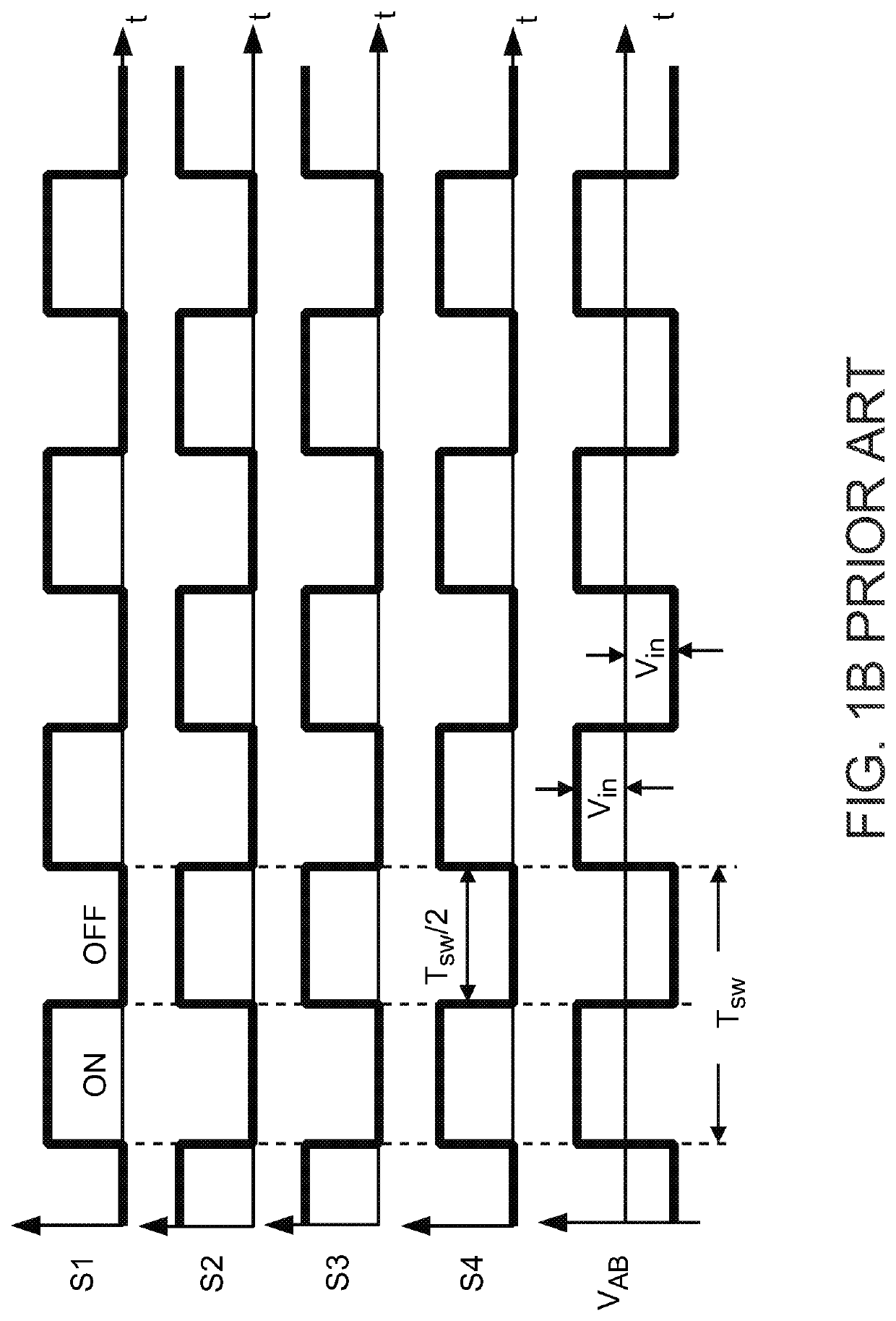
Efficiency, however, always diminishes as switching frequency fsw moves away from resonant frequency fr.
To achieve a wide output voltage range, the LLC resonant converter operates at a very wide frequency range, which inevitably compromises its efficiency.
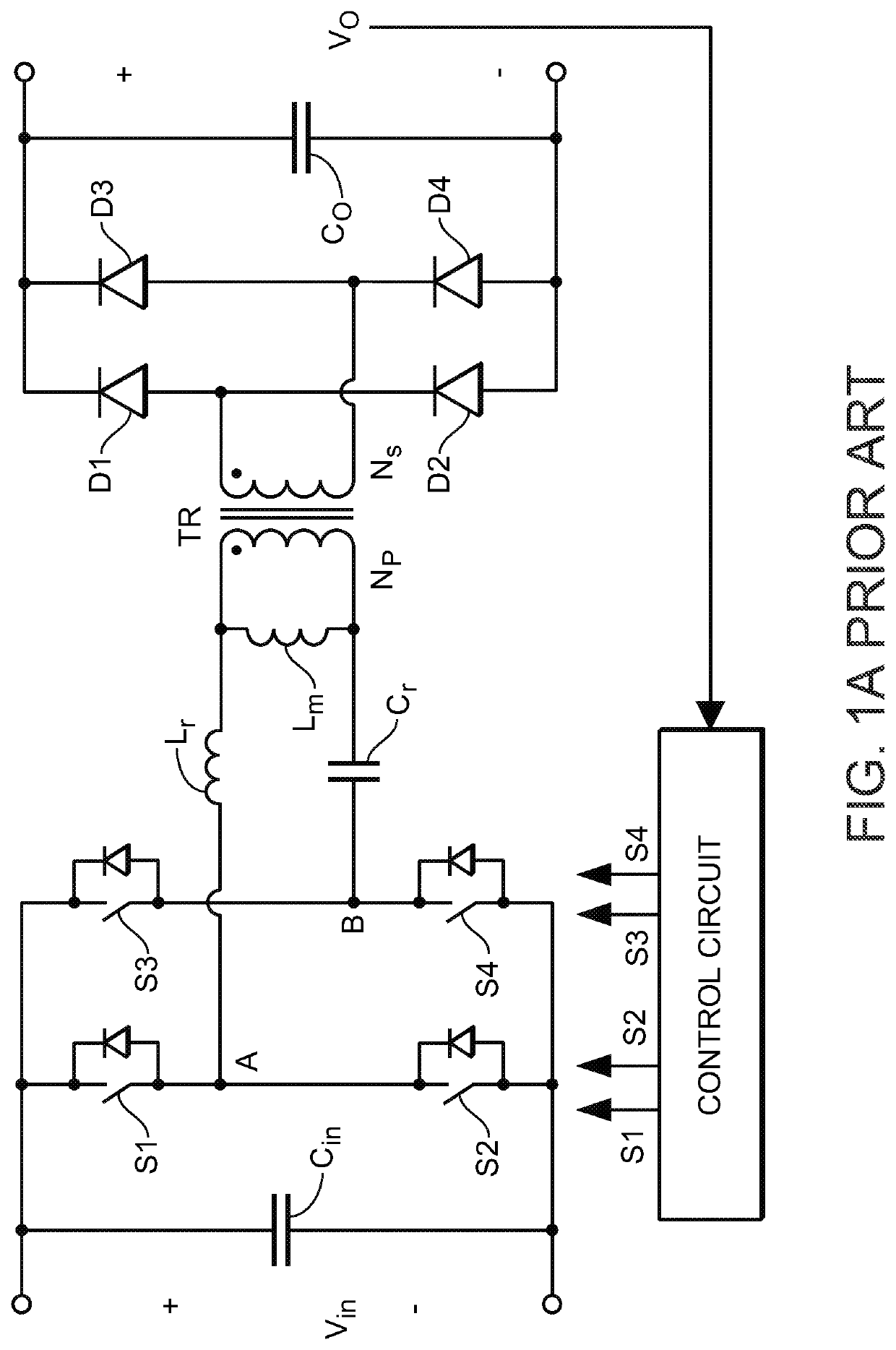
Further, as the maximum and minimum DC voltage gains of the LLC resonant converter are determined by such circuit parameters as the ratio of magnetizing inductance Lm to resonant inductance Lr, and by the load condition, the LLC resonant converter may be unable to achieve a very wide output voltage range under all load conditions.
Nevertheless, these techniques can only optimize the converter circuits to achieve a limited output voltage range (e.g., between 200 volts and 500 volts) in conventional EV charging applications.
However, these variations all have drawbacks, such as complexity in implementation, increased part count, or undesired dynamics.
In addition, these variations still do not achieve a sufficiently wide output voltage range.
One challenge in achieving a wide output voltage range is that the input voltage to the LLC resonant converter must be high enough to avoid an undesirably high DC gain.
As each switching device on the primary side is required to block the full input voltage (see, e.g., the LLC resonant converter shown in FIG. 1A), a higher input voltage results in an increased cost in high voltage components.
Under a three-level modulation scheme, however, the currents through the primary power switches are not balanced, which can cause thermal imbalance on the devices, shorten the device life and even lead to device damage.
However, Liu's gate signals of each half-bridge are not complementary, which increases the complexity of the gate driving circuit.
In addition, the body diode of the MOSFETs conducts current due to the non-optimized gate signals, which increases conduction loss and reduces system efficiency.

Method used


Image

  • Isolated dc/dc converters for wide output voltage range and control methods thereof
  • Isolated dc/dc converters for wide output voltage range and control methods thereof
  • Isolated dc/dc converters for wide output voltage range and control methods thereof

Examples


Embodiment Construction

[0047]The present disclosure will now be described more specifically with reference to the following embodiments. It is to be noted that the following descriptions of preferred embodiments of this disclosure are presented herein for purpose of illustration and description only. It is not intended to be exhaustive or to be limited to the precise form disclosed.

[0048]To avoid the higher cost associated with a higher input voltage, a multi-level topology may be used to maintain the same device voltage rating for the primary-side bridge. FIG. 7A shows a SHB topology (also known as “stacked buck topology”) that provides LLC resonant converter 700 that has a serial half-bridge on the primary-side. As shown in FIG. 7A, the serial half-bridge includes four series-connected switching devices S1 to S4, configured such that each switching device S1 to S4 blocks one-half of the input voltage across input terminals P and N. The input terminals P and N are provided across series-connected input c...


PUM


Abstract

An efficient control method for an isolated multilevel DC/DC resonant converter achieves a wide output voltage range with a narrow device switching frequency range, relative to the output voltage range and the device switching frequency range of the prior art. At any given time, a control circuit selects one of three different modulation schemes to operate the primary-side switching devices of the resonant converter based on at least one of output voltage, output current, input signal, and one or more external control signals. Together with a selected device switching frequency, the three modulation schemes generate different voltage waveforms to a primary-side transformer, which are coupled to the secondary-side to provide different output voltages.

Description

CROSS-REFERENCE TO RELATED APPLICATION[0001]This application is a continuation-in-part application of U.S. application Ser. No. 16 / 882,679 filed on May 25, 2020, which is a continuation-in-part application of U.S. application Ser. No. 16 / 551,543 filed on Aug. 26, 2019. The entireties of the above-mentioned patent applications are incorporated herein by reference for all purposes.FIELD OF THE INVENTION[0002]This invention relates to power converters. More specifically, this invention relates to controlling a resonant DC / DC converter using various modulation schemes to attain regulation of an output voltage over a very wide voltage range.BACKGROUND OF THE INVENTION[0003]Many power conversion applications (e.g., battery charging in electrical vehicles (EVs)) require a regulated output voltage over a wide voltage range. For example, a typical EV battery charger circuit has two converter stages: (i) a front-end AC / DC converter that provides either a fixed DC bus voltage or a variable DC ...

Claims


Application Information

Patent Timeline
Patent Type & Authority Applications(United States)
IPC IPC(8): H02M3/335G01R19/175G01R19/165H02M1/00
CPCH02M3/33576G01R19/175H02M3/33561H02M2001/0003H02M2001/0058H02M2001/009G01R19/16538H02M3/33569Y02B70/10H02M3/33546H02M3/01H02M1/0074H02M7/487H02M1/0003H02M1/009H02M1/0058
Inventor ZHANG, CHIBARBOSA, PETER
Owner DELTA ELECTRONICS INC
Why Eureka
Try Eureka