
Periodic Cellular Structure Based Design for Additive Manufacturing Approach for Light Weighting and Optimizing Strong Functional Parts

a functional part and additive manufacturing technology, applied in the field of additive manufacturing, can solve the problems of insufficient euclidean distance, insufficient sensitivity analysis and what-if analysis, and many minutes, hours or even days of single simulation

Pending Publication Date: 2021-07-15
THE RES FOUND OF STATE UNIV OF NEW YORK
View PDF2 Cites 12 Cited by
  • Summary
  • Abstract
  • Description
  • Claims
  • Application Information

AI Technical Summary

Benefits of technology

This patent text discusses the use of a material called CPCS to create lightweight and strong structures. By changing the shape of the material and the way it is arranged, the properties of the structure can be tuned. The text also introduces a method to optimize the filling of empty spaces in structures with CPCS to ensure strength and integrity under pressure. Overall, this patent offers a flexible way to create structures with unique properties by using CPCS.

Problems solved by technology

For many real-world problems, however, a single simulation can take many minutes, hours, or even days to complete.
As a result, routine tasks such as design optimization, design space exploration, sensitivity analysis and what-if analysis become impossible since they require thousands or even millions of simulation evaluations.
In many situations, the Euclidean distance is insufficient for capturing the actual distances in a given space.
In general, this process cannot be reversed: there is no consistent way to recover a coset of N from Lp.

Method used


Image

  • Periodic Cellular Structure Based Design for Additive Manufacturing Approach for Light Weighting and Optimizing Strong Functional Parts
  • Periodic Cellular Structure Based Design for Additive Manufacturing Approach for Light Weighting and Optimizing Strong Functional Parts
  • Periodic Cellular Structure Based Design for Additive Manufacturing Approach for Light Weighting and Optimizing Strong Functional Parts

Examples


Embodiment Construction

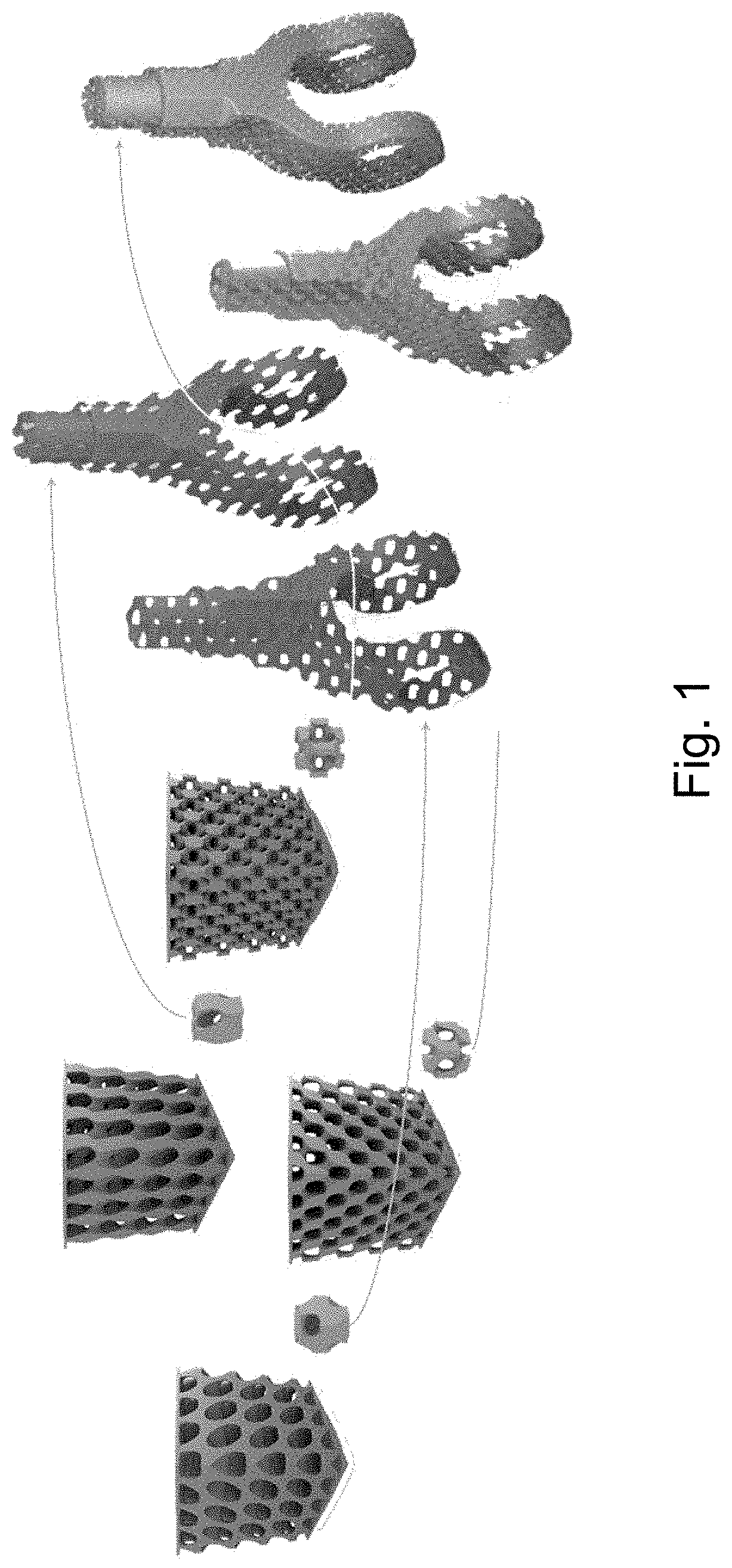
odic cellular structures (CPCSs) and lattified functional parts. Left: A set of different cubic periodic cellular structures are investigated to answer the research question: Can seemingly different geometries of the unit cell result in similar mechanical behaviors? Right: Illustrative example of a fork end made lighter by lattifying it with cubic periodic cellular structures filled inside. A surrogate model-based optimization framework allows optimization of the filling orientation to make light-weight and strong function parts under compressive loading environments.

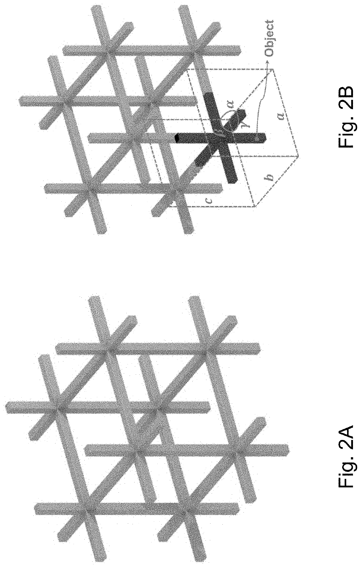
[0083]FIGS. 2A and 2B show cubic periodic cellular structure. FIG. 2A shows the simplest example of cubic periodic cellular structure with the repeating object as crossing square rods. FIG. 2B shows the unit cell repeats in a cubic phase where the edge length a=b=c and the interaxial angle α=β=γ=90°.

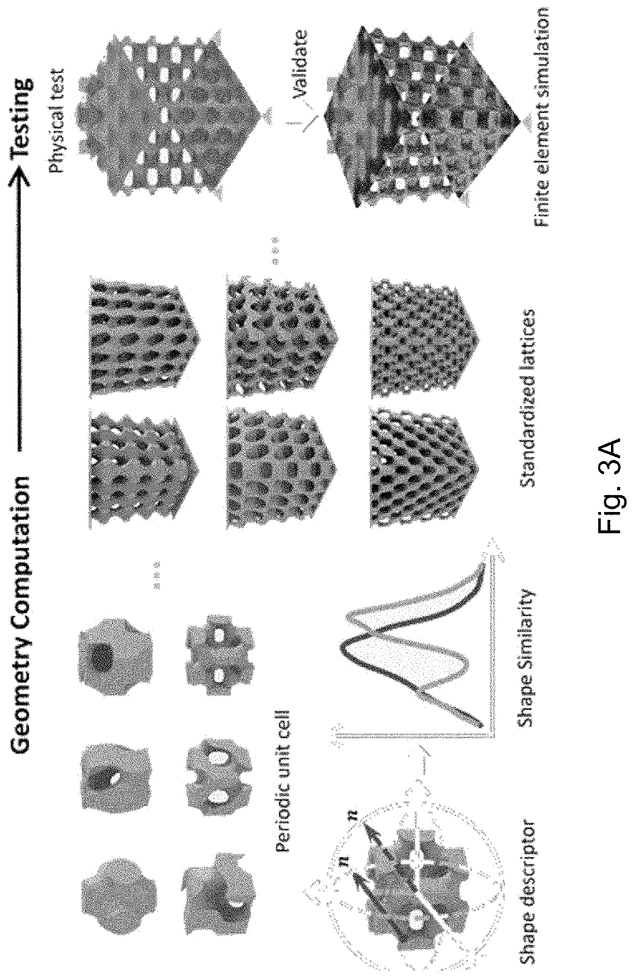
[0084]FIGS. 3A and 3B outline the flowchart showing the steps in the overall framework to optimize the lattified functiona...


PUM

PropertyMeasurementUnit
Fractionaaaaaaaaaa
Fractionaaaaaaaaaa
Fractionaaaaaaaaaa

Abstract

A method of additively manufacturing a 3D structure, comprising defining a boundary conditions, load constraints, and a periodic cell structure for lattifying the 3D structure; providing a surrogate FE model predicting a relationship between the boundary conditions, load constraints, periodic cell structure, and 3D orientation angle of the periodic cell structure; optimizing lattification of the 3D structure, according to orientation angle, and a cost function while meeting the load constraints; and additively manufacturing the optimized 3D structure, optimized e.g., for mass and stress concentration under a pre-determined loading condition.

Description

CROSS REFERENCE TO RELATED APPLICATIONS[0001]The present application is a non-provisional of, and claims benefit of priority under 35 U.S.C. § 119(e), from U.S. Provisional Patent Application No. 62 / 957,112, filed Jan. 3, 2020, the entirety of which is expressly incorporated herein by reference.FIELD OF THE DISCLOSURE[0002]The present disclosure relates to additive manufacturing, and more particularly, three-dimensional (3D) printing of structural components.BACKGROUND OF THE INVENTION[0003]Each reference cited herein is expressly incorporated herein by reference in its entirety.[0004]Nature is replete with fascinating examples of materials with intricate structures. Wegst and Ashby classified those natural materials into four groups: ceramics and ceramic composites, polymer and polymer composites, elastomers, and cellular materials. Among them, cellular materials are becoming of interest owing to the recent developments in cellular material design and additive manufacturing (AM). C...

Claims


Application Information

Patent Timeline
IPC IPC(8): G06F30/23B33Y80/00B29C64/386B33Y50/00
CPCG06F30/23B33Y80/00G06F2111/08B33Y50/00B29C64/386G06F2111/10G06F2119/14B33Y10/00B22F3/1115G06F2119/18
Inventor RAI, RAHULWANG, JUN
Owner THE RES FOUND OF STATE UNIV OF NEW YORK
Learn More