Bias circuit and electronic circuit

a bias circuit and electronic circuit technology, applied in the direction of amplifiers, electrical equipment, semiconductor devices, etc., can solve the problems of inability to supply stable bias voltage in the mass-produced products of bias circuits, inability to achieve stable performance in the mass-produced products of electronic circuits including bias circuits and external circuits

Active Publication Date: 2021-07-15
MURATA MFG CO LTD
View PDF0 Cites 0 Cited by
  • Summary
  • Abstract
  • Description
  • Claims
  • Application Information

AI Technical Summary

Benefits of technology

[0012]According to the present disclosure, it is possible to provide a bias circuit capable of supplying stable bias voltage and an electronic circuit including the bias circuit.

Problems solved by technology

In other words, stable bias voltage may not be supplied in mass-produced products of the bias circuit.
In addition, since an output signal output from the external circuit is also varied due to variation in the bias voltage, stable performance may not be achieved in the mass-produced products of the electronic circuit including the bias circuit and the external circuit.

Method used


Image

  • Bias circuit and electronic circuit
  • Bias circuit and electronic circuit
  • Bias circuit and electronic circuit

Examples


embodiment

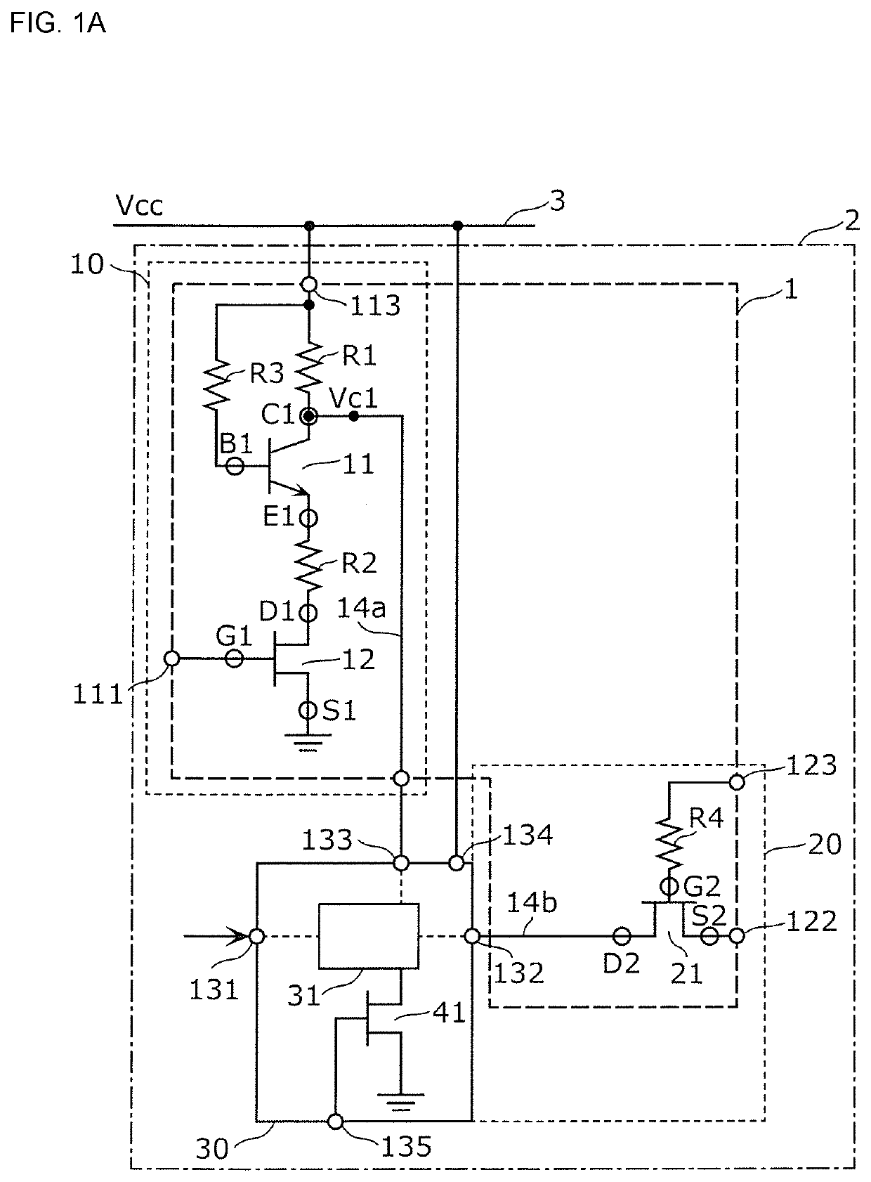
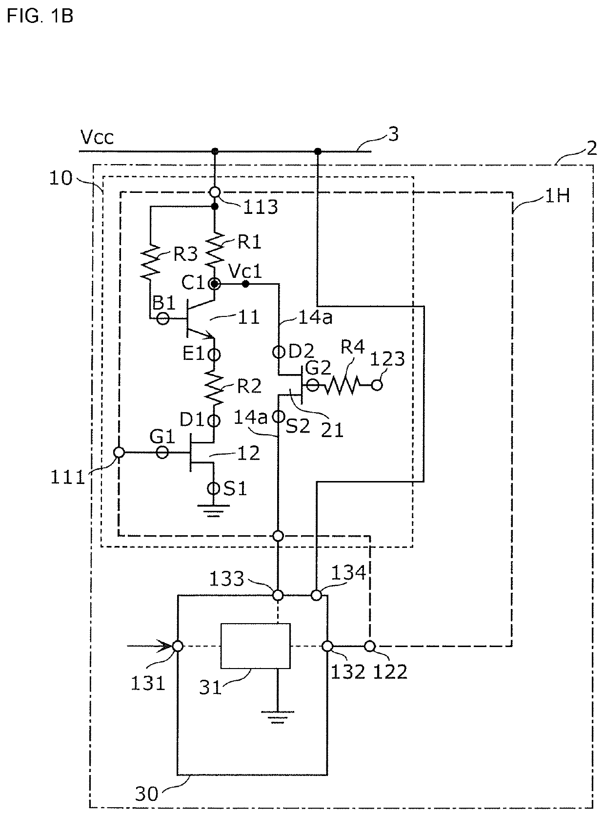
[0022]FIG. 1A is a circuit configuration diagram of a bias circuit 1 and an electronic circuit 2 according to an embodiment. As illustrated in FIG. 1, the electronic circuit 2 includes the bias circuit 1 and a linear detector circuit 30. The bias circuit 1 is a circuit that supplies bias voltage to the linear detector circuit 30. The linear detector circuit 30 is an external circuit that receives the bias voltage when the linear detector circuit 30 is viewed from the bias circuit 1. The external circuit is not limited to the linear detector circuit and may be another circuit, such as a normal detector circuit.

[0023]The linear detector circuit 30 has an input terminal 131, an output terminal 132, a bias terminal 133, a power supply terminal 134, and a detection unit 31. The linear detector circuit 30 receives, for example, a radio-frequency signal through the input terminal 131 and receives the bias voltage from the bias circuit 1 through the bias terminal 133. The detection unit 31 ...


PUM


Abstract

A bias circuit supplies bias voltage to a linear detector circuit. The bias circuit includes a transistor including a collector terminal, an emitter terminal, and a base terminal; a resistance element having one end connected to the collector terminal and the other end connected to a power line and the base terminal; a resistance element having one end connected to the emitter terminal; a transistor that switches between connection and disconnection between the resistance element and ground; collector voltage extended lines that transmit voltage corresponding to collector voltage as the bias voltage; and a transistor that is arranged on a path of one of the collector voltage extended lines and that switches between connection and disconnection between an output terminal of the linear detector circuit and the collector terminal.

Description

CROSS REFERENCE TO RELATED APPLICATION[0001]This is a continuation of International Application No. PCT / JP2019 / 037992 filed on Sep. 26, 2019 which claims priority from Japanese Patent Application No. 2018-185046 filed on Sep. 28, 2018. The contents of these applications are incorporated herein by reference in their entireties.BACKGROUNDTechnical Field[0002]The present disclosure relates to a bias circuit and an electronic circuit including the bias circuit.[0003]Patent Document 1 discloses the configuration of a regulator circuit including a depletion field effect transistor (FET) in which the drain terminal is connected to a power supply terminal, the source terminal is connected to an output voltage terminal, and the gate terminal is grounded via a diode. With this configuration, output voltage that is not affected by variation in power supply voltage is capable of being output while the FET is turned on or off in response to a control signal supplied to the gate terminal.[0004]Pa...

Claims


Application Information

Patent Timeline
Patent Type & Authority Applications(United States)
IPC IPC(8): H03K17/60
CPCH03K17/60H03F1/30H03F2200/105
Inventor YAMASHIRO, HIDEYOKAWANO, TAKAYUKI
Owner MURATA MFG CO LTD
Why Eureka
Try Eureka