Tooling pin placement system

a tooling pin and positioning system technology, applied in the direction of magnets, magnetic bodies, printing, etc., can solve the problems of product specificity, affecting the product quality, and affecting the placement of tooling pins, so as to reduce the magnetic attraction between the tooling pin and the support surface

Inactive Publication Date: 2021-07-22
ASM ASSEMBLY SYST SINGAPORE PTE LTD
View PDF0 Cites 4 Cited by
  • Summary
  • Abstract
  • Description
  • Claims
  • Application Information

AI Technical Summary

Benefits of technology

[0029]wherein the control means is operable to supply electrical power to the conductive coil to create a magnetic field which causes the magnetic attraction between the tooling pin and the support surface to be reduced.
[0035]iii) supplying electrical power to the conductive coil to create a magnetic field which causes the magnetic attraction between the tooling pin and the support surface to be reduced, and

Problems solved by technology

However, there are many circumstances where this type of arrangement is not possible, in particular where the underside of a workpiece has previously been printed and equipped with components (for example during a so-called “placement” operation), and this underside needs to be supported during a printing operation applied to the topside of the workpiece.
The presence of components on the underside of the workpiece means that the workpiece will not be flat, and also the components are liable to damage if they are “squashed” during a printing operation.
1) Dedicated tooling blocks—these are blocks whose upper surface is caused, for example by machining, to have a three-dimensional profile designed to accommodate a specific PCB placed thereon. They are relatively expensive, product-specific, and can easily become obsolete when a PCB design changes.
2) Magnetic tooling pins—these are thin columns which are positioned to contact the board in use, avoiding contact with any components (or other delicate or critical regions) on the underside. The pins are magnetic, i.e. they include either a permanent or an electro-magnet within them, to non-permanently attach the pins to a flat, underlying support plate or “tooling table”, which may conveniently be made from a magnetically permeable material such as steel. By way of example, ASM currently uses simple, low-cost, moulded plastics tooling pins with a single Neodymium permanent magnet in the base of each pin.
With a manual system it is challenging and time consuming for the operator to place the tooling pins consistently and with the required accuracy.
One reason why auto-place systems are problematic to implement for printing machines is that within a printing machine, there is generally only one place the pin-picker can be mounted in the printing machine without incurring significant extra cost and complexity, this being the camera gantry.
However, lifting a magnetic tooling pin away from the support plate can lead to such strain.
In a printing operation however, a large number of tooling pins may be required (typically a tooling set would include around 40 pins), and the solution described above becomes prohibitively expensive.
In this way, relatively complex and therefore expensive components are all contained within the pin-picker, with the tooling pin only containing the relatively simple, low-cost components.

Method used


Image

  • Tooling pin placement system
  • Tooling pin placement system
  • Tooling pin placement system

Examples


first embodiment

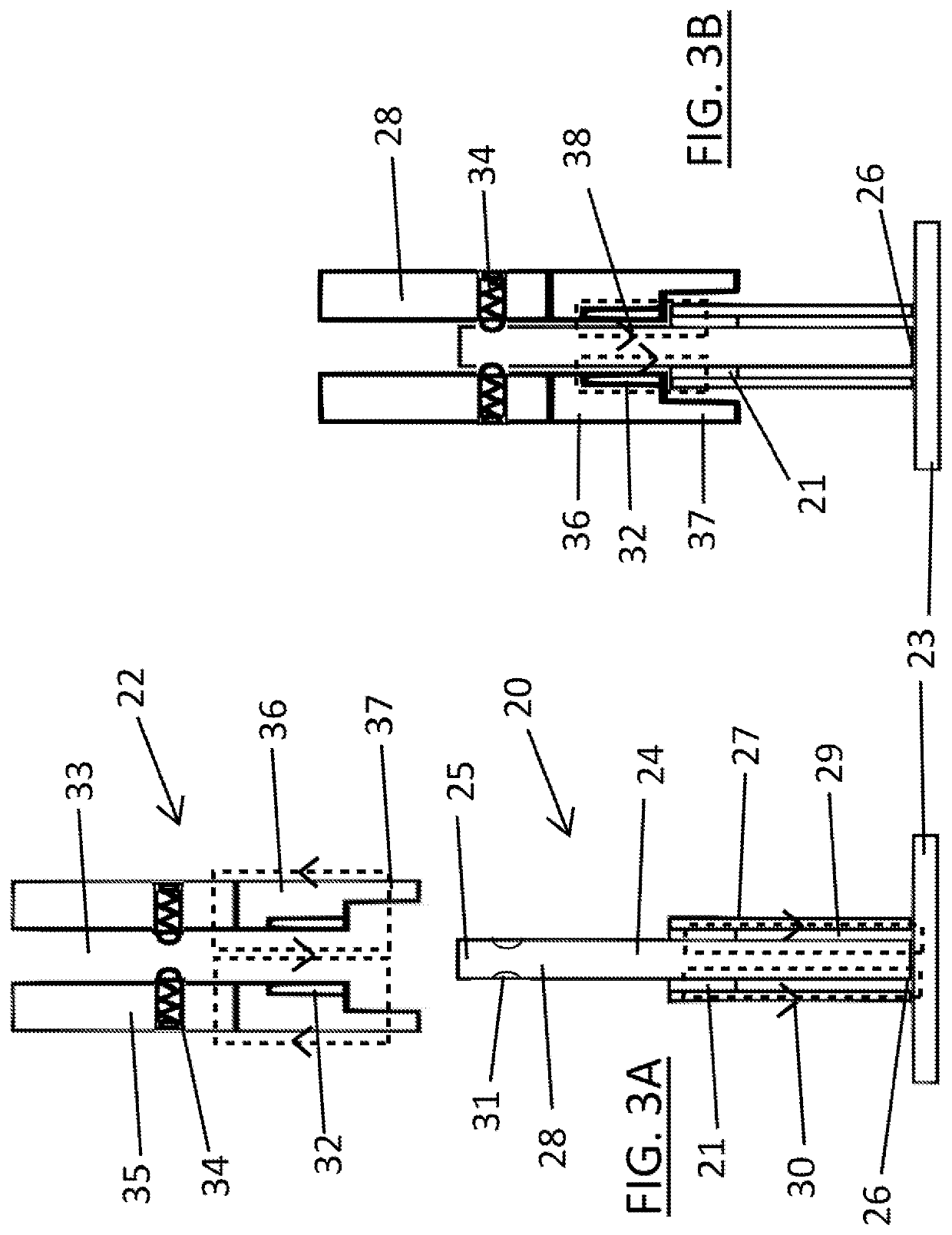
[0044]the present invention is schematically shown in FIGS. 3A and 3B, which show, in sectional view, a tooling pin 20 having a radially-magnetised permanent pin magnet 21 and an engagement body 22 of a pin-placement tool, in separated and engaged configurations respectively.

[0045]FIG. 3A shows the tooling pin 20 as it may be positioned during a printing operation for example, resting on and supported by a support surface 23 of a tooling table, the support surface being planar and formed from a ferromagnetic and therefore permeable material, such as steel for example. For clarity, only a small part of the support surface 23 is shown in FIGS. 3A and 3B, and it is to be understood that in practice it may extend over a large enough area to underlie a range of sizes of workpieces and accommodate many tooling pins. The tooling pin 20 comprises a pin body 24, here formed from a rigid and magnetically permeable material, such as steel for example. The permeability of the pin body material ...

second embodiment

[0049]the present invention is schematically shown in FIGS. 4A and 4B, which show, in sectional view, a tooling pin 40 having an axially-magnetised permanent pin magnet 41 and an engagement body 42 of a pin-placement tool, in separated and engaged configurations respectively. This embodiment is of particular utility where a tooling pin 40 with a relatively thin (for example in comparison to that shown in FIG. 3A) upper body section 48 is required. Many of the components are generally similar to those previously-described with reference to FIGS. 3A and 3B, and so need not be described further here. In particular, for clarity no mechanical latching mechanism is shown.

[0050]The pin magnet 41, which could for example be formed from high energy NdFeB, is here axially magnetised, i.e. parallel to the vertical length of the tooling pin 40, to produce an associated magnetic field 50, with flux lines passing vertically through the pin magnet 41, constrained within a lower body section 47, in...

third embodiment

[0053]FIGS. 5A-C schematically show, in sectional view, a tooling pin 60 and an engagement body 62, being part of a pin-placement tool, in accordance with the present invention, during a magnetic latching sequence. Many of the components are generally similar to those previously-described with reference to FIGS. 3A and 3B, and so need not be described further here.

[0054]FIG. 5A shows the engagement body 62 and tooling pin 60 in a mutually engaged configuration, in a default state, which would occur for example as soon as the engagement body 62 has been moved into an engaging position with tooling pin 60. The tooling pin 60, which is standing on a support surface 23, here comprises a substantially cylindrical pin body 64, for example formed from a moulded, e.g. an injection-moulded, electro-static dissipative plastics material, which houses a soft magnet 61, such as magnetised steel, at its lower end. As shown, the soft magnet's South pole is located at the lower end of tooling pin 6...


PUM


Abstract

A method of removing a magnetic tooling pin from a planar ferromagnetic support surface, comprises providing a pin-placement tool comprising an engagement body and an electrically conductive coil, supplying electrical power to the conductive coil to create a magnetic field which causes the magnetic attraction between the tooling pin and the support surface to be reduced, and moving the engagement body and engaged tooling pin away from the support surface.

Description

[0001]This invention relates to a tooling pin placement system, a printing machine, a placement machine and a method of removing a tooling pin from a planar ferromagnetic support surface.Background and Prior Art[0002]Industrial screen-printing machines typically apply a conductive print medium, such as solder paste or conductive ink, onto a planar workpiece, such as a circuit board, by applying the conductive print medium through a pattern of apertures in a printing screen (sometimes referred to as a mask or stencil) using an angled blade or squeegee.[0003]To ensure high quality printing, it is necessary to support the workpiece so that the surface to be printed is parallel to the printing screen, generally horizontal, with the workpiece support being capable of withstanding the pressure placed upon it during the printing operation, especially by the downward pressure applied by the squeegee, while maintaining the correct alignment of the workpiece. The simplest type of support is t...

Claims


Application Information

Patent Timeline
Patent Type & Authority Applications(United States)
IPC IPC(8): B41F15/14
CPCB41F15/14B41P2215/10H05K13/0069H05K3/1225H05K3/341H05K2203/0165B41F15/18H05K3/1216B41F15/0881H05K13/0061H05K2203/104H01F7/0231H01F7/04H01F7/122
Inventor FALCON, TOMPAPE, SIMON STUART
Owner ASM ASSEMBLY SYST SINGAPORE PTE LTD
Why Eureka
Try Eureka