
Storage system and control method of storage system

a storage system and control method technology, applied in the field of storage system and control method of storage system, can solve the problems of increasing the failure recovery time, reducing reliability and availability, and unable to scale out the capacity and performance of a user volume in proportion to the number of servers, so as to reduce the concentration of load due to failover

Inactive Publication Date: 2021-07-22
HITACHI LTD
View PDF0 Cites 0 Cited by
  • Summary
  • Abstract
  • Description
  • Claims
  • Application Information

AI Technical Summary

Benefits of technology

The invention aims to reduce the load concentration caused by failover in a storage system. The technical effect of the invention is to decrease the concentration of data processing requests during failover situations.

Problems solved by technology

As data to be stored in a storage increases, a storage data capacity per node also increases, and a data rebuilding time at the time of recovery of a server failure is lengthened, which leads to a decrease in reliability and availability.
In this method, by switching the access path of the LU to the recovered server after recovery of the server failure, it is possible to recover from failure without data rebuilding, but unlike the distributed storage system shown in Patent Literature 1, it is impossible to scale out capacity and performance of a user volume in proportion to the number of servers.
In the data rebuilding, it is necessary to rebuild data for a recovered server based on the redundant data on other servers via a network, which increases a failure recovery time.
However, in the distributed file system constituting a huge storage pool across all servers, load distribution after the failover is a problem.
As a result, the failover destination server becomes overloaded and access response time deteriorates.

Method used


Image

  • Storage system and control method of storage system
  • Storage system and control method of storage system
  • Storage system and control method of storage system

Examples


first embodiment

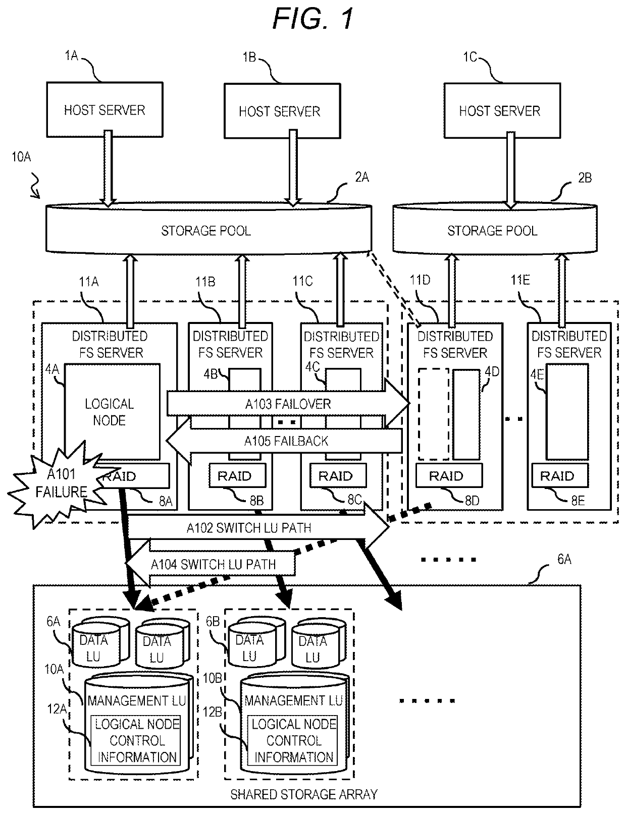
[0044]FIG. 1 is a block diagram showing an example of a failover method of a storage system according to a

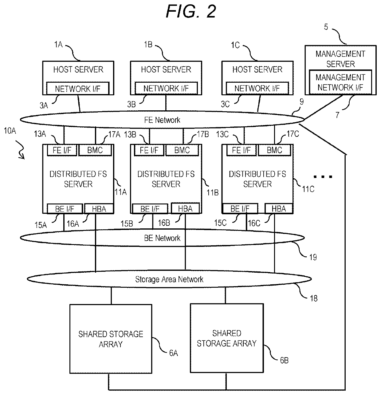
[0045]In FIG. 1, a distributed storage system 10A includes N (N is an integer of two or more) distributed FS servers 11A to 11E, and a shared storage array 6A including one or more shared storages. The distributed storage system 10A constructs a distributed file system in which a file system for managing files is distributed to N distributed FS servers 11A to 11E based on logical management units. On the distributed FS servers 11A to 11E, logical nodes 4A to 4E, which are components of a logical distributed file system, are respectively provided, and there is one logical node for each of the distributed FS servers 11A to 11E in an initial state. The logical node is the logical management unit of the distributed file system and is used in a configuration of a storage pool. The logical nodes 4A to 4E operate as one node constituting the distributed file system like physical server...

second embodiment

[0238]FIG. 22 is a flowchart showing an example of a storage pool creation processing of the storage system according to the

[0239]In FIG. 22, in this storage pool creation processing, the processing of S155 is added between the processing of S150 and the processing of S160 of FIG. 15.

[0240]In the processing of S155, the management program P17 calculates the number of logical nodes NL per distributed FS server with respect to the target availability α. At this time, the number of logical nodes NL can be given by the following Formula (2).

NL=11-α-1(Formula2)

[0241]For example, when the target availability is set to 0.75, the number of logical nodes per distributed FS server is 3. In the case where the availability is 0.75 when the number of logical nodes is 3, a resource usage rate per logical node is 0.25, so that the resource usage rate is 1 or less even if the failover occurs in another distributed FS server.

[0242]After S160, the management program P17 prepares a logical node corres...


PUM


Abstract

To reduce load concentration due to failover. A distributed storage system includes: a plurality of distributed FS servers; and one or more shared storage arrays. The distributed FS servers include logical nodes, which are components of a logical distributed file system, the plurality of logical nodes of the plurality of servers form a distributed file system in which a storage pool is provided, and anyone of the logical nodes processes user data input to and output from the storage pool and inputs and outputs the user data to and from the shared storage array, and the logical node is configured to migrate between the distributed FS servers.

Description

BACKGROUND OF THE INVENTION1. Field of the Invention[0001]The present invention relates to a storage system and a control method of a storage system.2. Description of the Related Art[0002]As a storage destination of large-capacity data for artificial intelligence (AI) and big data analysis, a scale-out type distributed storage system whose capacity and performance can be expanded at low cost is widespread. As data to be stored in a storage increases, a storage data capacity per node also increases, and a data rebuilding time at the time of recovery of a server failure is lengthened, which leads to a decrease in reliability and availability.[0003]US Patent Application Publication 2015 / 121131 specification (Patent Literature 1) discloses a method in which, in a distributed file system (hereinafter referred to as distributed FS) including a large number of servers, data stored in a built-in disk is made redundant between servers and only service is failed over to another server when th...

Claims


Application Information

Patent Timeline
Patent Type & Authority Applications(United States)
IPC IPC(8): G06F3/06
CPCG06F3/0617G06F3/067G06F3/0647G06F3/0644G06F3/0635G06F2201/865G06F11/2094G06F11/2023
Inventor FUKATANI, TAKAYUKIHAYASAKA, MITSUO
Owner HITACHI LTD
Learn More