

On-board tank for the drainage of an aircraft engine
a technology for aircraft engines and reservoirs, applied in the field of aeronautical propulsion, can solve problems such as difficult integration and potential sources of environmental pollution
- Summary
- Abstract
- Description
- Claims
- Application Information
AI Technical Summary
Benefits of technology
Problems solved by technology
Method used
Image

Examples
Embodiment Construction
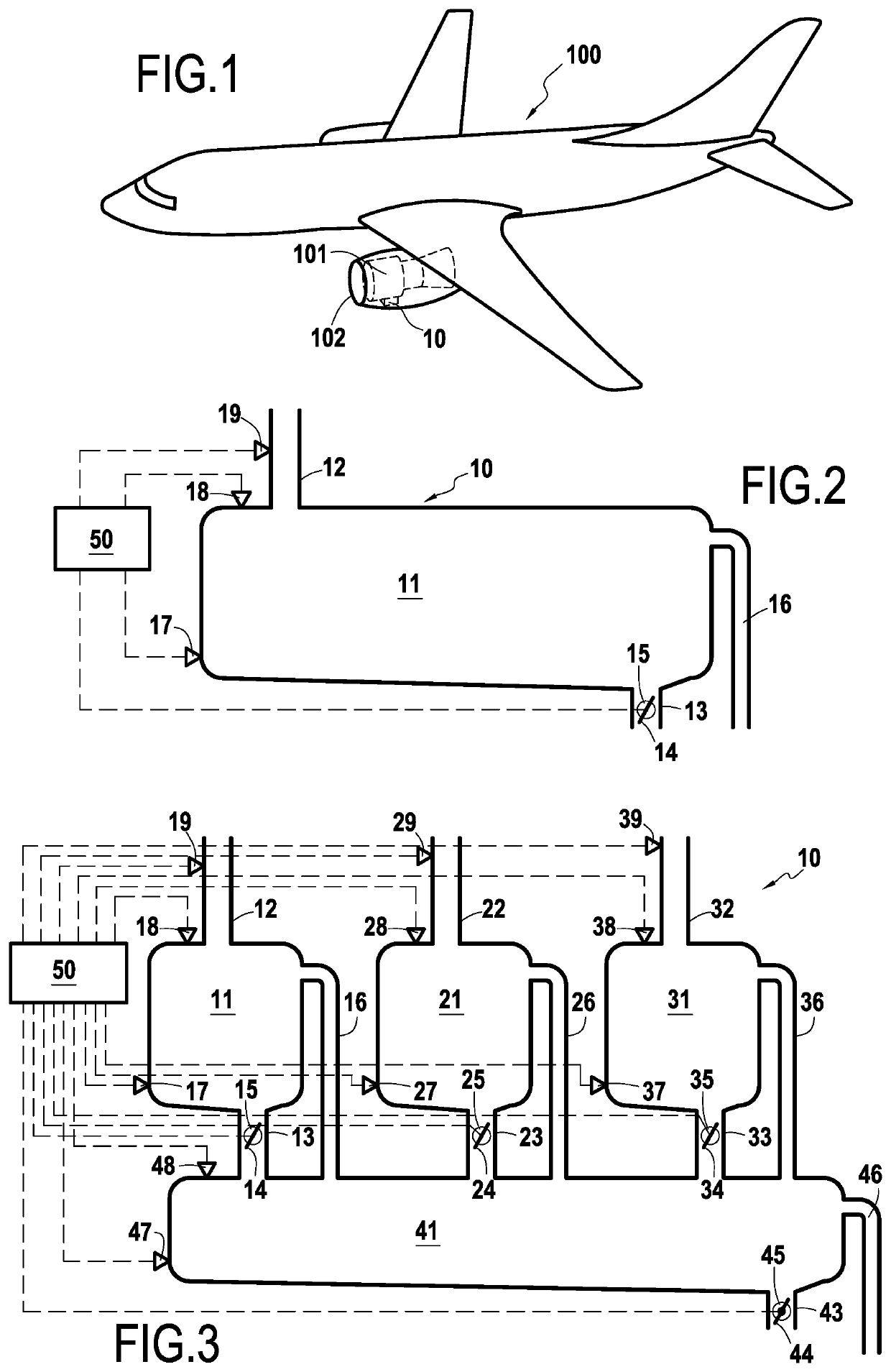
[0020]FIG. 1 illustrates an aircraft 100 equipped with two engines 101, which can in particular be gas turbine engines, and more particularly turbofans. As in the illustrated embodiment, each of these two engines 101 can be equipped with a on-board drainage reservoir 10, intended to receive fluids drained from the engine 101, such as for example lubricant escaping from the rotating shaft support bearings of the engine 101 and / or fuel escaping from the fuel supply circuit of the engine 101 and / or from actuators using this fuel as a hydraulic fluid. Thus, this reservoir 10 can allow avoiding that these fluids escape outside the engine in an uncontrolled manner, and thus constitute a source of environmental pollution.
[0021]To this end, the reservoir 10 can be situated below the engine 101, in a nacelle 102 surrounding it, and have a first compartment 11 with, for example at its vertex, a first intake passage 12 for fluid drained from the engine 101. The fluids escaping from the engine ...
PUM
 Abstract
Description
Claims
Application Information