Lift Truck Hoist Attachment

a technology for hoisting and trucks, which is applied in the direction of hoisting equipment, load-engaging elements, lifting devices, etc., can solve the problems of pole tents, center poles may even be damaged or knocked out from underneath the tent, and the center poles may be damaged or knocked ou

Pending Publication Date: 2021-08-12
RAM INDS
View PDF16 Cites 0 Cited by
  • Summary
  • Abstract
  • Description
  • Claims
  • Application Information

AI Technical Summary

Benefits of technology

[0014]Specifically, the fair lead assembly is not only able to travel along the length of the fair lead mounting posts, but is also able to rock forward and rearward. This rocking capability may be the result of slotted holes where the fair lead assembly connects to the fair lead mounting posts, and / or may simply be a result of sufficient clearance between the holes in the fair lead assembly and the fair lead mounting posts. In any case, if the load being lifted by the hoist cable reaches between about 20 and 30 degrees from vertical, particularly in the forward direction, sufficient travel is imparted to the high limit switch arm that the high limit switch, whether or not embodied as a reversing solenoid, is triggered, which then shuts off the hoist, and / or reverses the hoist momentarily. This off-vertical cutoff functionality further protects against tipping the lift truck and Lift Truck Tent Hoist Attachment.
[0015]As further protection against breakage of the hoist cable or other components of the Lift Truck Tent Hoist Attachment, the hoist cable may be provided with a cable buffer spring. The cable buffer spring is arranged over the hoist cable between the cable buffer and the jay hook. In this way, when the cable buffer contacts the fair lead assembly of the combination limit switch, buffer, and vertical shutoff switch, and the high limit switch is triggered, additional travel is provided by the cable buffer spring in the event that the amount of travel provided by the fair lead springs is insufficient to compensate for the rotational inertia of the hoist and any lag time of the high limit switch. It is noted that the compression force of the cable buffer spring is chosen to be at least as stiff, in this case being 700 pounds per inch and 4½″ long, as the compression force of the fair lead springs. This ensures that the fair lead assembly of the combination limit switch, buffer, and vertical shutoff switch initially travels sufficiently to trigger the high limit switch.

Problems solved by technology

However, pole tents have a drawback in that the center poles present an obstacle in the occupied area beneath the tent, along with guide ropes around the perimeter of the tent.
In a worst case scenario, such center poles may even be damaged or knocked out from underneath the tent.
Furthermore, pole tents are not engineered to withstand significant snow or wind loads.
A difficulty involved with clear span tents is the fact that the rafters or simple trusses, along with the side legs, must be lifted and pivoted into a straight up position when the structure is being assembled.
These machines are often expensive, heavy, and rated far in excess of the actual lifting weight capacity that is actually needed.
Additionally, such equipment often requires specially licensed personnel to operate.
However, the hoist has significant rotational inertia, so that the hoist cable continues to withdraw for an inch or two.
It is not intended for heavy loads even within the rated lifting capacity of the lift truck or other equipment having forks, nor is it intended for pulling, towing, or lateral loads.

Method used


Image

  • Lift Truck Hoist Attachment
  • Lift Truck Hoist Attachment
  • Lift Truck Hoist Attachment

Examples


first embodiment

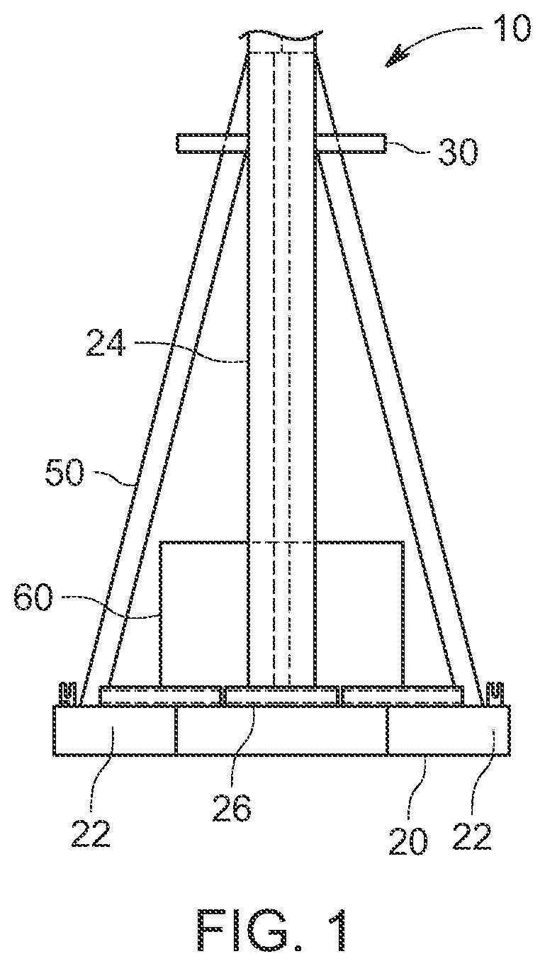
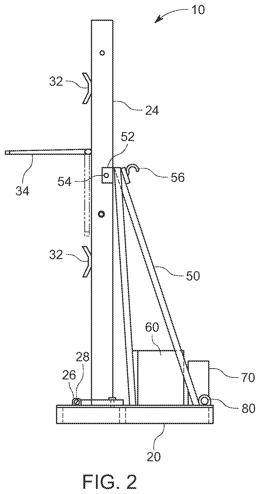
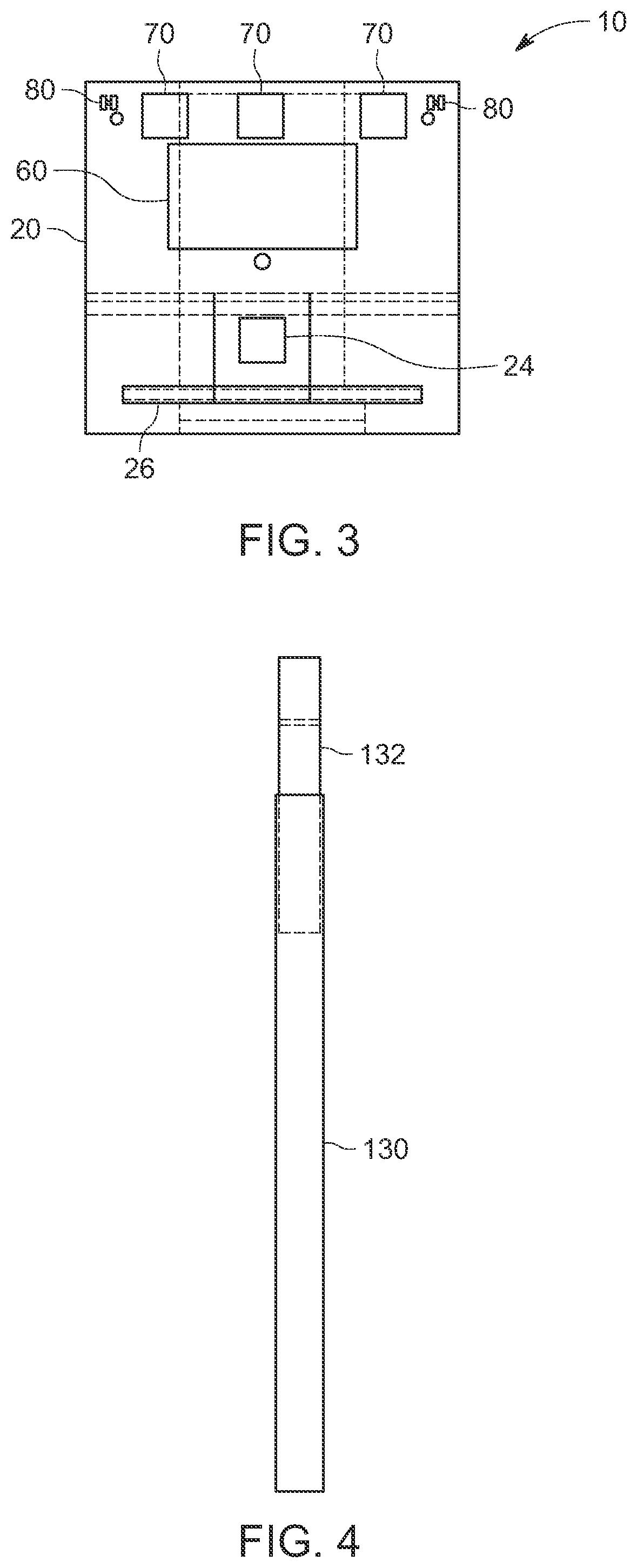
[0044]Turning now to FIGS. 1 through 7, the Lift Truck Tent Hoist Attachment 10 is shown having a base 20 and a lower mast 24 connected to the base 20 by way of a lower mast pivot hinge 26. The base 20 is provided with two fork pockets 22 configured to receive the forks of a forklift (not shown) or other equipment having forks. The base 20 is further provided with a lower mast brace assembly 50 having a receiver 52. The lower mast brace assembly 50 is arranged so that at least one support strut is oriented generally vertically and proximate to the lower mast, and so that at least one support strut is oriented at an angle extending rearward from the receiver 52. When the lower mast 24 is in its vertical position, it engages with the receiver 52 and is held in place by a brace pin 54. The Lift Truck Tent Hoist Attachment 10 also has an upper mast 90 and one or more intermediate mast extensions 130. The upper mast 90 is slidably engageable with the lower mast 24 and with the one or mor...

second embodiment

[0058]Turning now to FIGS. 13 and 14, the Lift Truck Tent Hoist Attachment 210 is shown having a base 220 and a lower mast 224 connected to the base 220 by way of a lower mast pivot hinge 226. The base 220 is provided with two fork pockets 222 configured to receive the forks of a forklift (not shown) or other equipment having forks. The base 220 is further provided with a lower mast brace assembly 250 having a receiver 252. The lower mast brace assembly 250 is arranged so that at least one support strut is oriented generally vertical and proximate to the lower mast, and so that at least one support strut is oriented at an angle extending forward from the receiver 252. When the lower mast 224 is in its vertical position, it engages with the receiver 252 and is held in place by a brace pin (not shown). The Lift Truck Tent Hoist Attachment 210 also has an upper mast 290 and one or more intermediate mast extensions 330. The upper mast 290 is slidably engageable with the lower mast 224 a...


PUM


Abstract

A lower mast is attached to a base having fork pockets, and is pivotal between vertical and horizontal positions. A lower mast brace assembly has a receiver configured to receive the lower mast as it is moved into the generally vertical position, and to retain it there. An upper mast having a hoist at its upper end slides into the lower mast. The upper mast has a dogleg that offsets the hoist forward of the centerline of the lower mast. A hook is attached to the lower mast brace assembly near the receiver. The hinge, the lower mast brace assembly, the dogleg of the upper mast, and the hook are arranged so that the hoist may be used to pull the mast from the horizontal position to the vertical position. A combination limit switch, buffer, and vertical shutoff switch may be attached to the upper end of the upper mast.

Description

CROSS-REFERENCE TO RELATED APPLICATIONS[0001]The present application claims priority to U.S. Provisional No. 62 / 971,492 filed Feb. 7, 2020, the entire contents of all of which are herein incorporated by reference.BACKGROUNDField of Invention[0002]Embodiments of the present invention described herein generally relate to a Lift Truck Tent Hoist Attachment. The Lift Truck Tent Hoist Attachment is designed as a self-contained collapsible boom or mast assembly usable with a forklift or other piece of equipment that is provided with forks. The Lift Truck Tent Hoist Attachment allows for lifting lightweight loads to significantly increased heights over the normal vertical reach of the forklift or other piece of equipment that is provided with forks.Related Art[0003]Rental agencies often rent large tents for events such as parties, celebrations, festivals, sporting events, corporate events, concerts, and the like. Often, these tents are pole tents that are raised by securing at least a port...

Claims


Application Information

Patent Timeline
Patent Type & Authority Applications(United States)
IPC IPC(8): B66F9/12B66D3/24B66D3/26
CPCB66F9/12B66D3/26B66D3/24B66C23/30B66C13/16
Inventor MUTTON, ROBERT
Owner RAM INDS
Why Eureka
Try Eureka