Crucible cover for coating with an electron beam source

Pending Publication Date: 2022-01-20
FERROTEC USA CORP
View PDF3 Cites 0 Cited by
  • Summary
  • Abstract
  • Description
  • Claims
  • Application Information

AI Technical Summary

Benefits of technology

[0029]One advantage of the present invention is that the cover insert rests on, in, or around features of the cover body, so it can partially decouple from the cover body and seek its own height and levelness, when the cover body is lowered sufficiently. Alternatively, the cover insert can be partially secured to the cover body by means of a spring like element or elements which can provide additional downward force to the cover insert, thus increasing the force against the crucible.
[0030]Another advantage of the present invention is that when the cover body is lowered, the cover insert will also be lowered until the insert comes into contact with the crucible. At that point, the cover insert will stop its downward motion and remain in contact with the crucible, while the cover body continued its downward travel to its resting point. It is noted that the drawings illustrate the cover insert contacting a raised wall (dividing web structure) of the crucible that is located at an elevation above the crucible surface. This cover insert concept will work in other configurations as well, such as having the cover insert coming to rest on a surface near horizontal to the crucible surface, or a surface which is lower than the crucible surface, if the web structure is sufficiently short or not present.
[0031]A further advantage of the present invention is that the partial decoupling between the cover body and the cover insert reduces the need to set precise clearances and parallelisms between the cover and crucible in order to minimize or eliminate the gap between them. This is accomplished by design so that the cover body has sufficient over travel to insure that the cover insert comes into contact with the crucible at a wide range of dimensional variation during setup of the source assembly. This will also allow easier reassembly after servicing the so

Problems solved by technology

Those solutions rely on maintaining close tolerances in regions where toler

Method used


Image

  • Crucible cover for coating with an electron beam source
  • Crucible cover for coating with an electron beam source
  • Crucible cover for coating with an electron beam source

Examples


Embodiment Construction

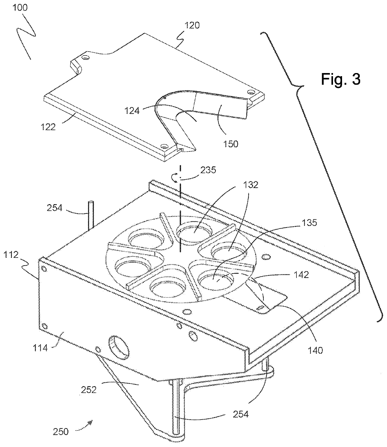
[0079]The present invention is illustrated in FIGS. 3-42. FIGS. 3-5 illustrate one embodiment of an evaporative source 100 of the present invention. A crucible 130 with six crucible pockets 132 is mounted inside of source housing 112. A variety of crucible materials and construction techniques are known to those skilled in the art, including but not limited to: crucibles with high thermal conductivity, low melting point materials, such as copper or aluminum, that incorporate water cooling; crucibles constructed out of high melting point materials such as graphite, tungsten, or molybdenum; and crucibles with graphite liners or those that use surface oxidation to limit thermal conductivity from the evaporant to the crucible surface.

[0080]The intersection of pockets 132 on the crucible surface 134 defines pocket edges 133 around each pocket. Crucible 130 may have more or fewer pockets, the choice of six pockets being for illustrative purposes only. The crucible is mounted to the source...


PUM

PropertyMeasurementUnit
Thicknessaaaaaaaaaa
Areaaaaaaaaaaa
Distanceaaaaaaaaaa

Abstract

A cover arrangement comprised of at least two pieces for covering a crucible within an electron beam source assembly. The cover includes a cover body and a cover insert to be separate from and carried by the cover body, when the cover body is raised and lowered. This arrangement also allows the cover insert to be lowered until it comes to rest on top of the crucible. Upon contact between the cover insert and the crucible, the cover insert can partially decouple from the cover body, allowing the cover body to travel down slightly further, allowing it to come into contact with the water-cooled body that surrounds the crucible, while insuring that the crucible insert is in good contact with the crucible. Closing this gap helps stop material that is evaporating from the active crucible pocket from migrating to inactive pockets, located under the cover, during the evaporation process.

Description

BACKGROUND OF THE INVENTION1. Field of the Invention[0001]The present invention relates generally to crucible covers for multiple pocket electron beam sources used in vacuum coating systems. Particularly, the present invention relates to crucible covers in which individual crucible pockets containing coating materials are heated to produce coating vapors. More particularly, the present invention relates to cooperating cover and crucible combinations that isolate heated pockets from all other pockets.2. Description of the Prior Art[0002]Vacuum coating or deposition of materials is a process commonly used in the manufacture of a variety of products including, but not limited to, semiconductors, optics, and the formation of thermal barriers on high temperature components. One method for coating materials having very small vapor pressures, such as metals or ceramics, is by placing the coating material and a workpiece to be coated in a vacuum chamber, reducing the pressure (typically in ...

Claims


Application Information

Patent Timeline
IPC IPC(8): C23C14/24C23C14/30
CPCC23C14/243C23C14/30F27B14/12C23C14/564H01J2237/3132
Inventor KRONEBERGER, CRIS
Owner FERROTEC USA CORP
Why Eureka
Try Eureka