Supercharge Your Innovation With Domain-Expert AI Agents!

Successive approximation ad converter

a technology of approximation and converter, applied in the field of approximation ad converter, can solve the problems of differential nonlinear error of transitional change, constant unevenness of integral nonlinear error, etc., and achieve the effect of improving the integral nonlinear error

Active Publication Date: 2021-08-12
ASAHI KASEI ELECTRONICS CO LTD
View PDF0 Cites 1 Cited by
  • Summary
  • Abstract
  • Description
  • Claims
  • Application Information

AI Technical Summary

Benefits of technology

The patent describes a way to improve the accuracy of an analog-to-digital converter by using a successive approximation method. This method helps to reduce errors caused by non-linear effects, without the need for calibration. The technical effect of this invention is to provide a more accurate and reliable analog-to-digital conversion process.

Problems solved by technology

Accordingly, the total sum of unevenness of all the DA conversion elements contributing to the transitional change constitutes the differential nonlinear error.
However, an integral nonlinear error which is an accumulation of errors in element unevenness is constant between the two DA converters when the element unevenness is the same.
The amount of unevenness of the elements changes depending on a manufacturing tolerance, but since the amount of unevenness does not change with the same total number of elements, unevenness of the integral nonlinear error is constant.
However, in order to perform calibration by measuring an element mismatch as in the related art, a control circuit that performs a measuring sequence, a circuit that calculates a correction code, a memory that stores the correction code, and the like are required and thus a circuit area and costs increase.

Method used


Image

  • Successive approximation ad converter
  • Successive approximation ad converter
  • Successive approximation ad converter

Examples


first embodiment

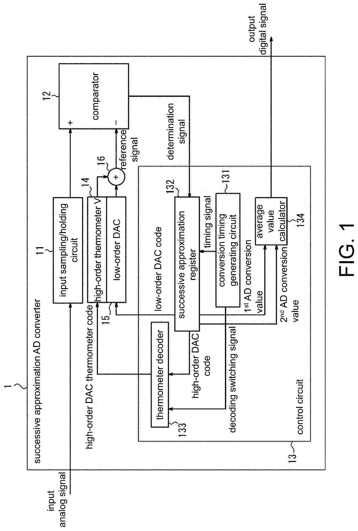
[0037]A successive approximation AD converter according to a first embodiment will be described below. FIG. 1 is a block diagram illustrating an example of a configuration of the successive approximation AD converter according to the first embodiment. The successive approximation AD converter 1 illustrated in FIG. 1 includes an input sampling / holding circuit 11, a comparator 12, a control circuit 13, a high-order thermometer DAC (first DA converter) 14, a low-order DAC (second DA converter) 15, and a reference signal generator 16.

[0038]The input sampling / holding circuit 11 samples and holds an input analog signal.

[0039]The comparator 12 compares the input analog signal held in the input sampling / holding circuit 11 with a reference signal, and generates a judge signal indicating a result of comparison to the control circuit 13. The reference signal is a signal which is generated by the reference signal generator 16.

[0040]The control circuit 13 includes a conversion timing generating ...

second embodiment

[0077]A successive approximation AD converter according to a second embodiment will be described below. As described above, the INL waveform changes by switching the decoding method, but a difference thereof is a peak-peak value of the waveforms at most. That is, it means that there is only two times an amount of error of the maximum INL error in a successive approximation AD conversion result obtained by performing conversion using the first decoding method at most. In an AD converter of eight bits including the DA converter illustrated in FIG. 16, a conversion range thereof is ±128 codes.

[0078]FIG. 7 is a diagram illustrating an example of a conversion error which is caused by causing the thermometer decoder 133 to switch the thermometer code conversion rule. Here, the same integral nonlinear error as illustrated in FIG. 4 is illustrated, and a conversion error of -6 codes is generated after the first thermometer code conversion rule has been switched to the second thermometer cod...

third embodiment

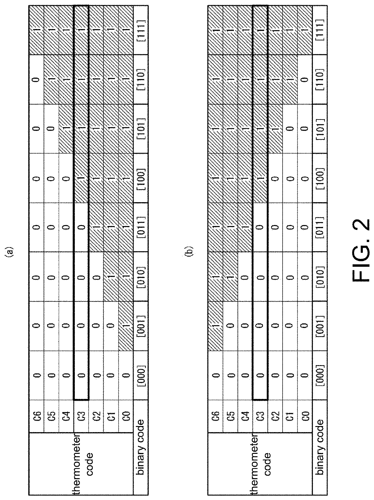
[0096]A successive approximation AD converter according to a third embodiment will be described below. In the first embodiment and the second embodiment, the thermometer decoder 133 converts the high-order DAC code to different high-order DAC thermometer codes using two types of thermometer code conversion rules in one cycle of AD conversion. On the other hand, in this embodiment, the thermometer decoder 133 converts the high-order DAC code to different high-order DAC thermometer codes using four types of thermometer code conversion rules in one cycle of AD conversion.

[0097]FIG. 12 is a block diagram illustrating an example of a configuration of a successive approximation AD converter 3 according to the third embodiment. The successive approximation AD converter 3 according to this embodiment is different from the successive approximation AD converter 1 according to the first embodiment, in that a control circuit 13b is provided instead of the control circuit 13. Only differences fr...


PUM


Abstract

A successive approximation ADC includes: a comparator generating a judge signal related to an input analog and a reference signals; a SAR successively generating a register signal including a first and a second bit signals based on the judge signal and generating an AD conversion value of the input analog signal; a thermometer decoder switching different thermometer code conversion rules and converting the first bit signal to thermometer codes corresponding to the different thermometer code conversion rules in one AD conversion cycle; a first and a second DA converters respectively converting the thermometer codes to a first analog signal and the second bit signal to a second analog signal; an average value calculator averaging the AD conversion values by the thermometer codes. Two of the different thermometer codes have values that a high-order bit and a low-order bit groups by dividing total bits of the thermometer code equally are exchanged.

Description

CROSS REFERENCE TO RELATED APPLICATIONS[0001]This application claims the priority benefit of Japanese Patent Application No. 2020-020110, filed on Feb. 7, 2020. The entirety of the above-mentioned patent application is hereby incorporated by reference herein and made a part of this specification.BACKGROUNDTechnical Field[0002]The disclosure relates to a successive approximation AD converter.Description of Related Art[0003]A successive approximation AD converter is known as an AD converter that converts an input analog signal to a digital signal. The successive approximation AD converter includes a DA converter, a comparator, and a successive approximation logical circuit. As an input of the DA converter, a binary code is converted to a thermometer code.[0004]In general, as a result of comparison between a DA converter using a binary code (a binary DA converter) and a DA converter using a thermometer code (a thermometer DA converter), a differential nonlinear error in the thermometer...

Claims


Application Information

Patent Timeline
Patent Type & Authority Applications(United States)
IPC IPC(8): H03M1/46H03M1/08
CPCH03M1/462H03M1/468H03M1/0809H03M1/0656H03M1/687H03M1/804H03M1/785H03M1/765
Inventor KONNO, SHOTA
Owner ASAHI KASEI ELECTRONICS CO LTD
Features
  • R&D
  • Intellectual Property
  • Life Sciences
  • Materials
  • Tech Scout
  • Unparalleled Data Quality
  • Higher Quality Content
  • 60% Fewer Hallucinations
Learn More