Region correction apparatus, region correction method, and region correction program

Pending Publication Date: 2021-08-19
FUJIFILM CORP
View PDF0 Cites 0 Cited by
  • Summary
  • Abstract
  • Description
  • Claims
  • Application Information

AI Technical Summary

Benefits of technology

[0032]According to the present disclosure, it is possible to correct the boundary of t

Problems solved by technology

However, in a case of automatically extracting the region of interest, over-extraction and under-extraction may occur.
However, in a case of correcting the boundaries of the regions of interest included in the tomographic images, the boundaries in a direction in which the tomographic images are arranged may not be smoothly connected to each other.
When the three-dimensional image is viewed in a direction intersecting the direction in which the tomographic images are arranged, the boundaries of the re

Method used


Image

  • Region correction apparatus, region correction method, and region correction program
  • Region correction apparatus, region correction method, and region correction program
  • Region correction apparatus, region correction method, and region correction program

Examples


Example

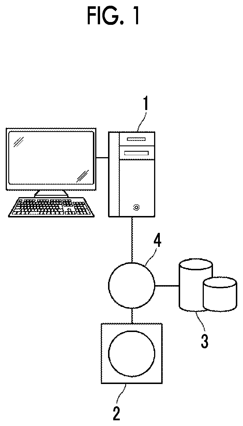
[0047]Hereinafter, an embodiment of the present disclosure will be described with reference to the drawings. FIG. 1 is a hardware configuration diagram showing an outline of a diagnosis support system to which a region correction apparatus according to the embodiment of the present disclosure is applied. As shown in FIG. 1, in the diagnosis support system, a region correction apparatus 1, a three-dimensional image capturing apparatus 2, and an image storage server 3 according to the present embodiment are connected to communicate with one another via a network 4.

[0048]The three-dimensional image capturing apparatus 2 is an apparatus that generates a three-dimensional image representing a site of a subject as a diagnosis target by capturing the site, and specific examples thereof include a CT apparatus, an MRI apparatus, and a positron emission tomography (PET) apparatus. The three-dimensional image generated by the three-dimensional image capturing apparatus 2 is transmitted to and ...


PUM


Abstract

The display controller displays a first tomographic image of a three-dimensional image consisting of a plurality of tomographic images on a display unit. A first correction unit corrects the boundary of a first region of interest extracted from the first tomographic image, by a correction instruction using a correction instruction region for the boundary of the first region of interest. The first instruction region setting unit sets a first instruction region on a second tomographic image of the plurality of tomographic images. The second correction unit corrects the boundary of a second region of interest extracted from the second tomographic image by setting a second instruction region on the second tomographic image.

Description

CROSS REFERENCE TO RELATED APPLICATIONS[0001]The present application is a Continuation of PCT International Application No. PCT / JP2019 / 040490 filed on Oct. 15, 2019, which claims priority under 35 U.S.C. § 119(a) to Japanese Patent Application No. 2018-205733 filed on Oct. 31, 2018. Each of the above applications is hereby expressly incorporated by reference, in its entirety, into the present application.BACKGROUNDTechnical Field[0002]The present disclosure relates to a region correction apparatus, a region correction method, and a region correction program that correct the boundary of a region of interest extracted from a three-dimensional image.Related Art[0003]In recent years, advances in medical equipment such as a computed tomography (CT) apparatus and a magnetic resonance imaging (MRI) apparatus have made it possible to perform diagnostic imaging using a higher quality three-dimensional image having higher resolution. A region of interest such as an organ and a lesion included...

Claims


Application Information

Patent Timeline
IPC IPC(8): G06T11/00G06K9/32A61B6/03A61B6/00G06V10/25G06V10/44G06V10/98
CPCG06T11/008G06K9/3233G06K2209/05A61B6/463A61B6/032G01T1/161A61B5/055G06T19/20A61B6/469A61B6/037A61B6/5205A61B6/5217G06T2207/10081G06T5/006G06N3/08G06N20/00G06V10/98G06V10/25G06V10/44G06V2201/03G06T2211/441
Inventor SAKURAGI, FUTOSHI
Owner FUJIFILM CORP
Why Eureka
Try Eureka