Leak-resistant vaporizer device

a vaporizer and leak-resistant technology, applied in the field of vaporizer equipment, can solve the problems of clogging the device, disturbing the electrical components, and a more serious consideration and challenge for leakag

Active Publication Date: 2021-09-02
JUUL LABS INC
View PDF0 Cites 4 Cited by
  • Summary
  • Abstract
  • Description
  • Claims
  • Application Information

AI Technical Summary

Benefits of technology

[0014]For example, a cartridge as described herein may include a vaporizable material such as cannabis oil. Cannabis oils present particular challenges when vaporized using a cartridge and / or a handheld vaporizer device. For example, cannabis oil is relatively “sticky” and may be viscous, particularly once it dries out. Thus, leakage may be a more serious consideration and challenge compared to other aqueous vaporizable materials. In particular, leakage of cannabis oil may result in clogging of the device and disturbing the electrical components, particularly the electrical contacts, which may be otherwise “gummed up” by leaked oil. The dried oil is not only sticky, but may also be electrically insulative, and may disrupt the electrical control of the vaporizer. Described herein are apparatuses and methods to prevent or control leakage and to avoid disruption of electrical contacts between cartridges containing the cannabis extract and the rest of the vaporizer.
[0016]Any of the cartridges described herein may include a tank or storage region within the cartridge and / or forming a portion of the body of the cartridge. In particular, all or a portion of the cartridge (including the tank) may be clear, transparent and / or translucent so that the level of vaporizable material within the tank can be seen by a user. The tank may be prefilled or fillable. The tank may be sealed closed at the top (near the mouthpiece, which may cover the top of the cartridge). The mouthpiece may be plastic and may be secured over the tank by a snap fit, a friction fit, and adhesive, or the like. For example, the distal end of the elongate and flattened tubular body is configured to be secured by a friction fit within a vaporizer body. As described in greater detail herein, one or more absorbent members, (e.g., sponges, pads, felts, etc.) may be included in the mouthpiece between the tank and the mouthpiece, to prevent leakage of vaporizable material from contacting the portion of the mouthpiece where the user applies her or his lips. The tank may be sealed, e.g., by a tank seal that covers the one or more openings for filling the tank. In some variations, rather than one or more small plugs (which may be difficult to install) the tank may be sealed by a multi-seal component (e.g., a single piece) that seals between the mouthpiece and the top of the tank as and closes off two or more openings into the tank.
[0019]Drawing on the mouthpiece typically causes airflow to enter the cartridge receiver region of the vaporizer base through one or more (e.g., two) air openings that are positioned through the wall of the cartridge receiver near a base of the cartridge receiver. Air may pass into the cartridge receiver and up through the cartridge via one or more openings in the base (bottom) of the cartridge. The air may then pass into a heater connector region that also includes one or more (e.g., two, parallel) absorbent pads or sponges for absorbing any leakage of vaporizable material that may enter into this air-filled heater connector region, which is also open to the vaporizing chamber across which a wick and heating coil is extended to form vapor. The two absorbent pads positioned in this air region positioned on the long axis of the cartridge, against the major faces of the cartridge body so that they don't block the air path into the vaporization chamber from the opening(s) at the base. These absorbent pads (e.g., sponges) may prevent dripping or leakage of the fluid from the vaporization chamber (e.g., off of the wick) even when the heater is not being heated. In order to prevent leakage should the absorbent pads not be sufficient, the opening into the base of the air chamber may include a rim or boss on the inner surface (within the heater connector region at the base of the cartridge) that prevents small amounts of fluid (e.g., vaporization fluid such as cannabis oil) to drip out of the opening(s) into the cartridge (e.g., the air chamber of the cartridge).
[0024]In any of the variations described herein it may be useful to provide an indication of the amount of the cartridge vaporized, which may be approximately correlated to the dose of the vaporizable material delivered. In any of the apparatuses described herein, the apparatus may include an output (e.g., LED, LCD or other display, etc.) on the apparatus or on a device in communication (e.g., wireless communication) with the apparatus such as a smartphone, laptop, desktop, pad, or the like. The output may indicate a qualitative and / or quantitative amount of the dose of vapor delivered from a particular cartridge. Dose may be determined using the processor of the apparatus to indicate approximately how much of the material, e.g., cannabis oil, has been consumed based on the power applied to the heater and the duration of heating. A qualitative output may be provided by sequentially illuminating (and / or changing the intensity and / or color of illumination) of a plurality of LEDs. In another example a ‘status bar’ showing consumption or dose delivered from a cartridge may be displayed on the apparatus body (e.g., the vaporizer body) or another device (e.g., smartphone) in communication therewith. For example, a plurality of LEDs (RGB) may be illuminated to provide qualitative feedback to a user on the operation of the vaporizer. Upon inserting a cartridge, the vaporizer apparatus may display using the LEDs an illumination corresponding to the intensity of the inhalation and / or the progression of consumption of vaporizable material from the cartridge. The processor in the vaporizer apparatus may estimate a dose based on the power applied to the vaporizer and the duration of heating and / or the duration of draw (inhalation). For example, the power applied*duration of draw may be accumulated by the processor, and the value output. In some variations the output may be provided for display on the body of the apparatus (e.g., by illuminating a sequence of LEDs. This may provide immediate visual feedback to the user.
[0028]The one or more openings into the overflow leak chamber may be present on any surface of the cartridge, including through the distal end of the overflow leak chamber. Although placement of the opening at the distal end may otherwise result in an increase in leakage of the highly viscous oil from the cartridge, including the leak chamber and the absorbent pad(s) prevents or reduces leakage. In addition, the one or more openings may be surrounded by a lip within the leak chamber. The lip may have a height above the inner wall of the chamber that is 0.3 mm or greater (e.g., 0.5 mm or greater, 0.7 mm or greater, 0.8 mm or greater, 0.9 mm or greater, 1 mm or greater, 1.2 mm or greater, 1.3 mm or greater, 1.4 mm or greater, 1.5 mm or greater, 2 mm or greater, etc.).
[0040]The sizes of the openings into the air path (through the overflow leak chamber, e.g., at the distal end of the cartridge) may be configured to allow relatively easy draw through the cartridge, while preventing leakage out of the overflow leak path. Leaking may occur from the heater (e.g., the exposed wick) which is inserted through the wall of the tank; the air path within the cartridge is open and continuous, which would otherwise allow the material to leak. Thus, for example, the size of the one or more openings may be specified within a range identified as allowing sufficient air flow without permitting excessive leaking. For example, in some variations, the diameter of the opening(s) into the overflow leak chamber is / are between 0.1 mm and 5 mm (e.g., between 0.1 mm and 3 mm, between about 0.1 mm and 2 mm, etc.).

Problems solved by technology

Cannabis oils present particular challenges when vaporized using a cartridge and / or a handheld vaporizer device.
Thus, leakage may be a more serious consideration and challenge compared to other aqueous vaporizable materials.
In particular, leakage of cannabis oil may result in clogging of the device and disturbing the electrical components, particularly the electrical contacts, which may be otherwise “gummed up” by leaked oil.
The dried oil is not only sticky, but may also be electrically insulative, and may disrupt the electrical control of the vaporizer.

Method used


Image

  • Leak-resistant vaporizer device
  • Leak-resistant vaporizer device
  • Leak-resistant vaporizer device

Examples


Embodiment Construction

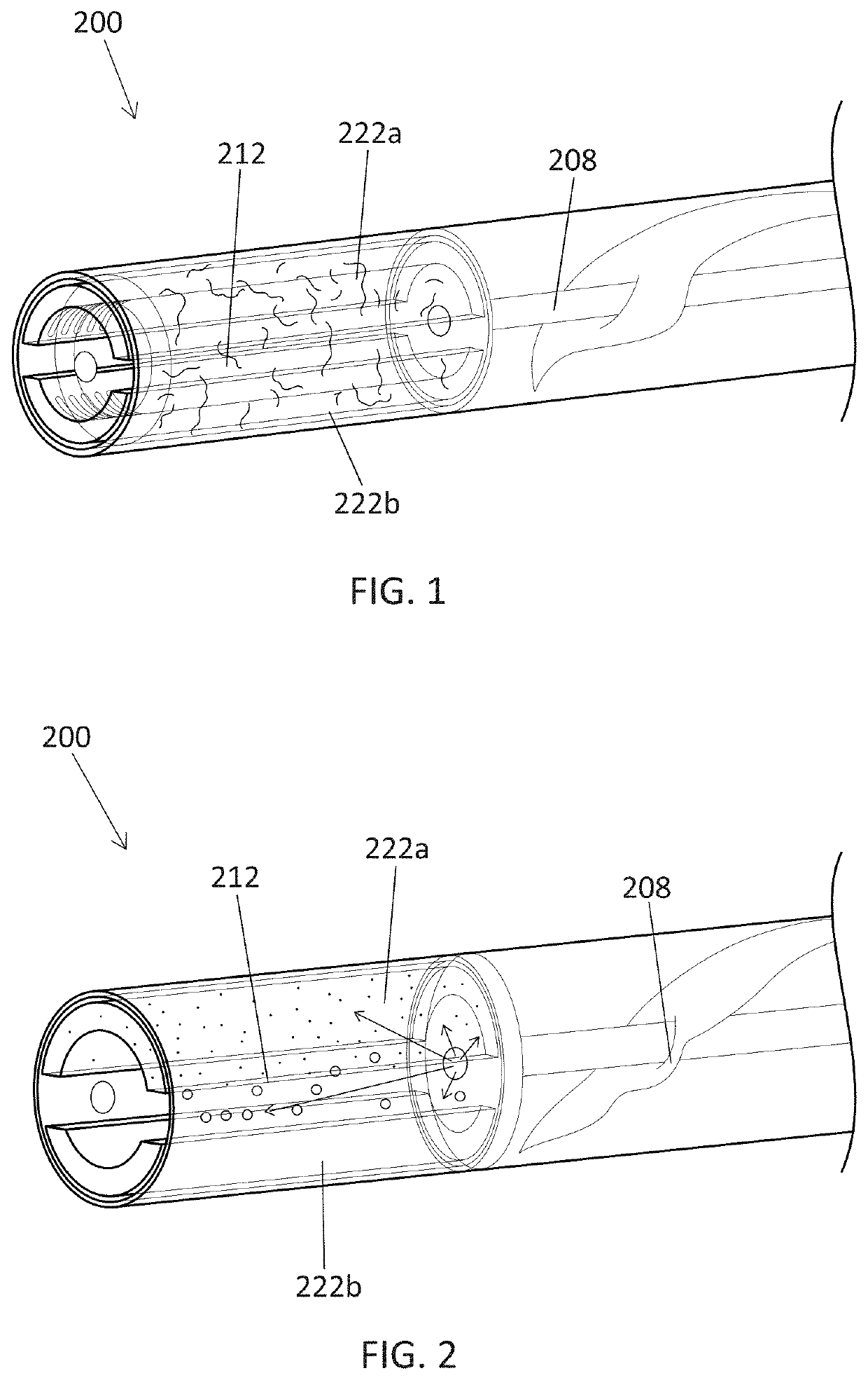
[0071]The apparatuses and methods described herein generally include forming a vapor from a material (including in particular, liquid and oil-type plant materials) using a vaporization device. The vapor may be delivered for inhalation by a user. These apparatuses may be particularly adapted for use with an oil-based vaporizable material, including cannabis oils.

[0072]The vaporizer apparatuses, including cartridges (vaporizer cartridges) and reusable vaporizers bases described herein may be used with any appropriate vaporizable material, including aqueous vaporizable materials. These apparatuses may be particularly well adapted for use with viscous, oil-based vaporizable materials, including cannabis oils. For example, any of the cartridges described herein may be used (e.g., filled) with a vaporizable material comprising viscous liquid such as a cannabis oil. In some variations the cannabis oil comprises between 40-100% cannabis oil extract. The viscous oil may include a carrier for...


PUM


Abstract

Vaporizer cartridges and vaporizer apparatuses, and methods for making, using and delivering vapor to a user, that are leak-resistant for use with cannabinoids. In particular, described herein are leak-resistant vaporizer cartridges and apparatuses adapted for use with oil-based vaporizable materials including cannabis oils.

Description

CROSS REFERENCE TO RELATED APPLICATIONS[0001]This patent application claims priority to U.S. Provisional Patent Application No. 62 / 341,579, titled “CONTROL OF AN ELECTRONIC VAPORIZER”, filed on May 25, 2016; U.S. Provisional Patent Application No. 62 / 351,272, titled “ELECTRONIC VAPORIZER DEVICES”, filed on Jun. 16, 2016; U.S. Provisional Patent Application No. 62 / 372,216, titled “ZERO-VOLUME STORAGE CONTAINERS FOR VAPORIZER CARTRIDGES”, filed on Aug. 8, 2016; and U.S. Provisional Patent Application No. 62 / 398,494, titled “VAPORIZER APPARATUSES FOR USE WITH CANNABINOIDS”, filed on Sep. 22, 2016; each of these patent application is herein incorporated by reference in its entirety.INCORPORATION BY REFERENCE[0002]All publications and patent applications mentioned in this specification are herein incorporated by reference in their entirety to the same extent as if each individual publication or patent application was specifically and individually indicated to be incorporated by reference...

Claims


Application Information

Patent Timeline
Patent Type & Authority Applications(United States)
IPC IPC(8): A61M11/00A24F40/40A61M11/04A61M15/06A24F40/10
CPCA61M11/00A24F40/40A24F40/10A61M15/06A61M2205/8206A61M11/042A24F40/46A24F40/42A24F40/57A61M15/0021A61M11/04A24B15/167A61M11/044A24F40/485A24F40/44A24F7/00A61M2205/121A61M2205/123
Inventor HATTON, NICHOLAS JAYCHRISTENSEN, STEVENLEON DUQUE, ESTEBANATKINS, ARIELMONSEES, JAMESBOWEN, ADAM
Owner JUUL LABS INC
Why Eureka
Try Eureka