Compact mechanical syringe extruder for 3D bioprinting of cell laden gels

a bioprinter and syringe technology, applied in the field of bioprinter system for fabricating system, can solve the problems of large volume of mechanical system, limited precision and simplicity, and damage to cells caused by pneumatic vacuum pressure through tubing or passage through long pneumatic tubing

Pending Publication Date: 2021-09-02
CEDARS SINAI MEDICAL CENT
View PDF0 Cites 1 Cited by
  • Summary
  • Abstract
  • Description
  • Claims
  • Application Information

AI Technical Summary

Benefits of technology

[0004]Described herein is a bioprinter for dispensing at least one biomaterial, comprising s processor configured to determine a path; a support assembly, comprising one or more linear rods; a gantry comprising: at least one extruder, each extruder comprising a nozzle and a tube, a plunger, a threaded shaft, a stepper motor, wherein the processor is operatively coupled to the support assembly to move the one or more linear rods along a determined path; and operatively coupled to the stepper motor, wherein the one or more linear rods are attached to the gantry, wherein the plunger is inside the tube and comprises a means for attachment to the threaded shaft, wherein the threaded shaft is mechanically coupled to the stepper motor, wherein the nozzle is at one end of the tube. In other embodiments, the means for attachment to the threaded comprises reciprocating members on each of the plunger and threaded shaft. In other embodiments, the reciprocating members are a snap fit coupling. In other embodiments, the bioprinter comprises two extruders. In other embodiments, the plunger is configured to exert pressure through the nozzle. Also described herein is a bioprinted assembly made by the bioprinter. In other embodiments, the bioprinted...

Problems solved by technology

While bioprinters exist on the market, including pneumatic and mechanical systems, they are significantly limited in precision and simplicity when exerting force to extrude materials on a surface, including bioinks with cells in a substrate.
For exa...

Method used


Image

  • Compact mechanical syringe extruder for 3D bioprinting of cell laden gels
  • Compact mechanical syringe extruder for 3D bioprinting of cell laden gels
  • Compact mechanical syringe extruder for 3D bioprinting of cell laden gels

Examples


example 1

[0035]Bioprinting may enable researchers to overcome limitations of current methods to construct macro-scale structures, organize different cell types together, and generate very specific shapes. To overcome size limitations, bioprinting is accomplished by generating a 3D computer model; generating a series of cross-sections of the model; then instructing a printhead to draw each cross-section and deposit material to construct the original 3D shape layer-by-layer.

example 2

[0036]Bioprinter incorporating stepper motor and threaded shaft

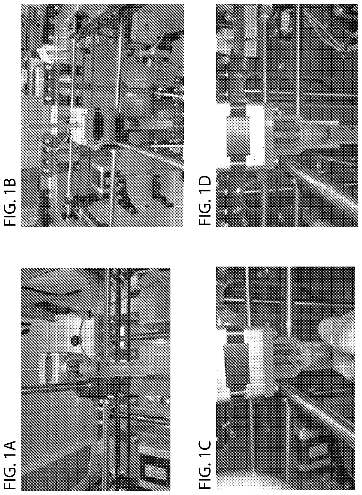
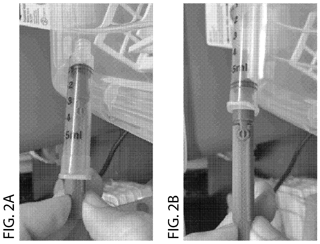
[0037]As shown in FIG. 1, the bioprinter includes a motorized extruder that obviates the needs for a bulky linear rail system. Whereas conventional designs couple a threaded shaft to a fixed shaft on a stepper motor, the stepper motor turns a threaded shaft directly. This obviates the need for pneumatic vacuum pressure systems and also reduces the gantry size, which allows for higher precision printing due to decreased weight removal of components that otherwise reduce tolerances due to mechanical play. The threaded shaft snaps into place for a plunger on a syringe, eliminating another source of mechanical play, by using a snap-fit coupling. The snap-fit coupling also allows easy loading and re-loading by providing for manual plunging of the syringe as shown in FIG. 2. Using a plunger extension that couples to the miniaturized plunger, the same snap coupling as the motor allows easy swapping. Another depiction of assembl...

example 3

[0038]Assembly and twin extruder design

[0039]An advantage of the system is that the simplified construction allows for multiple extruders to be assembled together, as shown in FIG. 6. In another perspective, the extruder is mounted on the assembly. In these designs, one could load two different bioink cell types in each extruder, or a cell type and other mechanical substrate in each extruder, with sequential or parallel fabrication, obviating the need to change bioinks / mechanical substrates, as is needed in conventional systems.


PUM

PropertyMeasurementUnit
Temperatureaaaaaaaaaa
Volumeaaaaaaaaaa
Volumeaaaaaaaaaa

Abstract

Bioprinting is the layer-by-layer construction of synthetic tissues or scaffolds. Described herein is a motorized extruder which can precisely extrude and retract extrudate such as bioinks in a compact and rapidly-loadable form-factor. This includes a compact bioprinter using a stepper motor coupled with a threaded shaft to directly move the plunger of an extruder. This pneumatic-mechanical system obviates the needs for pneumatic tubing, rods, or other complex elements of existing designs. The direct drive design further allows for a lighter, smaller gantry that is capable of more precise fabrication of bioprinted constructions. This includes delicate vasculature systems that are beyond limits of existing bioprinting technologies.

Description

FIELD OF THE INVENTION[0001]The described technology relates to a bioprinter system for fabricating systems including depositing cells in an organized fashion for analysis.BACKGROUND[0002]Bioprinting is the layer-by-layer construction of synthetic tissues or scaffolds in order to generate tissues with greater similarity to natural tissues for modeling organs (for research, such as drug discovery) and medicine (such as transplantation). While bioprinters exist on the market, including pneumatic and mechanical systems, they are significantly limited in precision and simplicity when exerting force to extrude materials on a surface, including bioinks with cells in a substrate. For example, pneumatic vacuum pressure through tubing may leak or transit through long pneumatic tubing is damaging to cells in bioink. Mechanical systems are bulky and need a large rod; a gantry surrounding the extruder is moved along the rod to exert pressure. There is a great need in the art for a system that a...

Claims


Application Information

Patent Timeline
IPC IPC(8): C12N5/071C12N5/074B33Y30/00B33Y70/00
CPCC12N5/0691C12N5/0696B33Y30/00B33Y50/02C12N2533/54C12N2533/52B33Y70/00A61L27/38A61L27/00B33Y80/00A61L27/3834A61L27/222A61L27/225
Inventor GROSS, ANDREW R.SAREEN, DHRUV
Owner CEDARS SINAI MEDICAL CENT
Why Eureka
Try Eureka