System and method for depth thermal imaging module

a thermal imaging module and thermal imaging technology, applied in the field of depth thermal imaging, can solve the problems of saturated ccd images, ccd camera cannot operate under normal lighting conditions, and conventional individual sensors fail in various ways, and achieve the effect of reducing nois

Active Publication Date: 2021-09-02
COMPERTUM MICROSYSTEMS INC
View PDF1 Cites 0 Cited by
  • Summary
  • Abstract
  • Description
  • Claims
  • Application Information

AI Technical Summary

Benefits of technology

[0026]The effects of noise are reduced by averaging corresponding pixels across the thermal images captured by the plurality of thermal imagers aimed in the same direction. The method then performs depth measurement by measuring disparity of the object of interest in thermal images captured by the plurality of thermal imagers aimed in the same direction.
[0027]Finally, the plurality of depth measurements is analyzed to extract meaning, make correlations, make relationships, predict effects, determine environment status / situation, etc. The results of the analysis are then transmitted to the vehicle CPU, an onboard control computer, or a remote computer server or network for responsive actions and / or instructions. As a result, the present invention obtains important data regarding the environmental status around the vehicle and allows the appropriate action to be taken by the vehicle.

Problems solved by technology

However, conventional individual sensors fail in various ways.
For example, a CCD camera can only operate under normal lighting conditions.
CCD images are saturated under sun glare and the CCD camera cannot effectively operate at night or in foggy conditions.
However, such IR flash operations can only work within close distances (<50 m).
On the other hand, Lidar is capable of operating at night for longer distance (<300 m); however, Lidar cannot function properly in a fog or snow environment due to light scattering and cannot work under sun glare conditions.
To date, there is no single sensor that can operate in most lighting and weather conditions.

Method used


Image

  • System and method for depth thermal imaging module
  • System and method for depth thermal imaging module
  • System and method for depth thermal imaging module

Examples


Embodiment Construction

"d_n">[0037]To facilitate understanding of the object, characteristics and effects of this present disclosure, embodiments together with the attached drawings for the detailed description of the present disclosure are provided.

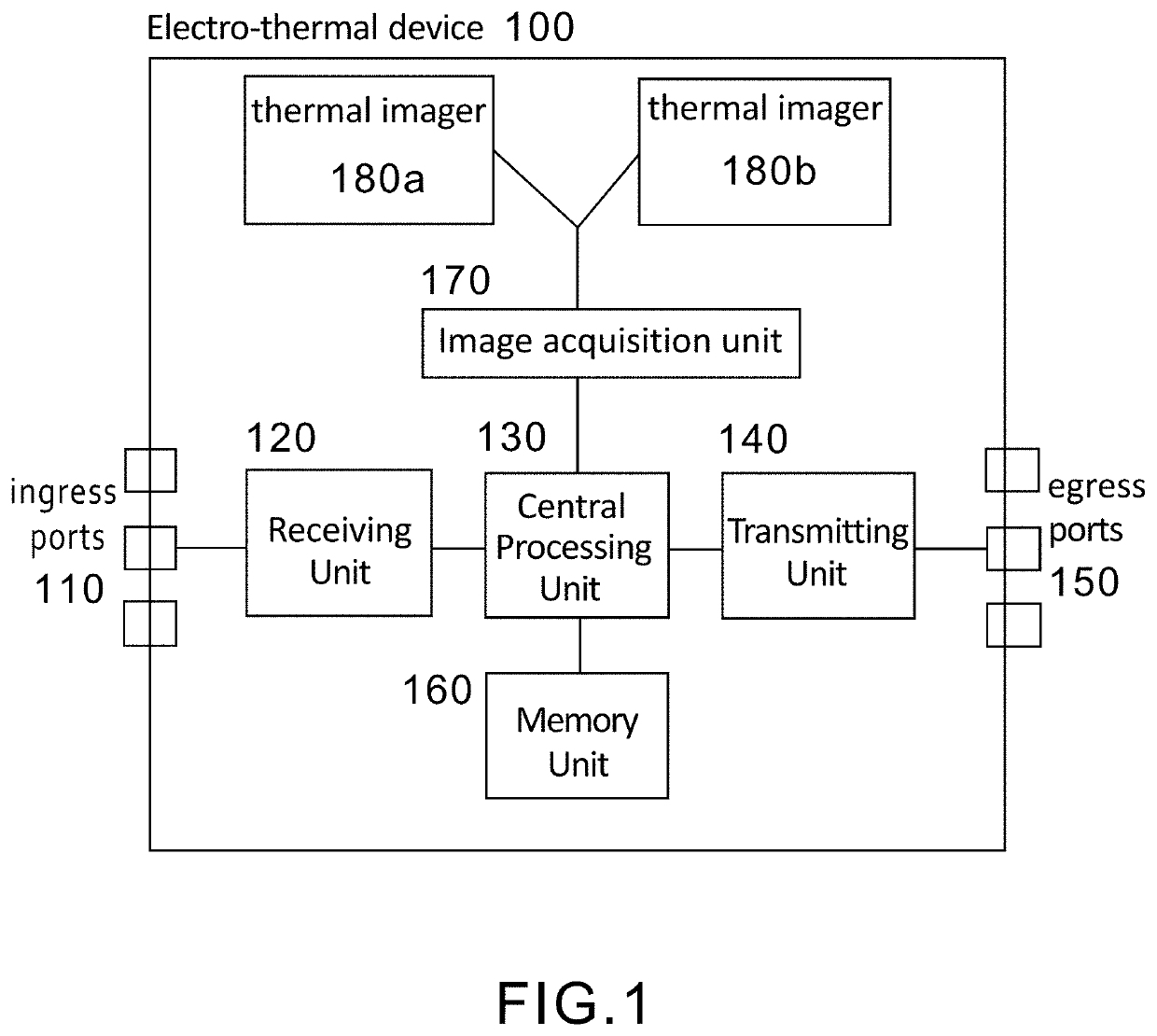
[0038]Refer to FIG. 1, which is a diagrammatic representation of an exemplary system of an electro-thermal module for depth thermal imaging according an embodiment of the present invention. The electro-thermal device 100 comprises ingress ports 110, at least one receiving unit (Rx) 120, a central processing unit 130, at least one transmitting unit (Tx) 140, egress ports 150, a memory unit 160, an image acquisition unit 170, and at least two thermal imagers 180a, 180b. In another embodiment, the at least two thermal imagers 180a, 180b are external but still connected to the electro-thermal device 100.

[0039]The ingress ports 110 are for connecting with various sensors, detectors, of data collectors / providers, for example, temperature sensors, shock sensors, vibr...


PUM


Abstract

A depth thermal imaging module, including a thermal imager array, which includes a plurality of at least two thermal imagers that capture thermal radiation of a wavelength of a scene from different viewpoints. Each thermal imager includes a thermal imager chip, a lens stack, and a focal plane with focal length f. The thermal imagers are separated by a baseline distance of 2h and depth measurement Z is performed on an object of interest based on Z=2hf/Δ where Δ is the difference in location of the object of interest between its location in the thermal image captured by a first thermal imager and the location of the object of interest in the thermal image captured by a second thermal imager and represents as an offset of the point on the focal plane of the first thermal imager and the second thermal imagers relative to their optical axis.

Description

CROSS-REFERENCE TO RELATED APPLICATION[0001]This non-provisional application claims priority under 35 U.S.C. § 119(e) on U.S. provisional Patent Application No. 62 / 982,082 filed on Feb. 27, 2020, the entire contents of which are hereby incorporated by reference.BACKGROUND OF THE INVENTION1. Field of the Invention[0002]The present invention relates to depth imaging, and in particular to a depth thermal imaging module comprising a thermal imager array for measuring depth of or distance to an object.2. Description of the Related Art[0003]To realize autonomous driving, a vehicle needs to process and interpret sensor information such as sensor data from a Charge-Coupled Device (CCD) camera, a Time Of Flight (TOF) camera (flash-IR-CCD camera), LIght Detection And Ranging (Lidar), radar, and a Global Positioning System (GPS) in order to navigate to a destination, identify its location within a multi-lane road, navigate alongside other vehicles, avoid obstacles and pedestrians, observe traf...

Claims


Application Information

Patent Timeline
Patent Type & Authority Applications(United States)
IPC IPC(8): G01J5/08H04N5/33G02B3/00
CPCG01J5/08G01J2005/0077G02B3/0062H04N5/33G01J5/0275G01J5/0806G01J5/20H04N13/271G01J5/80G01J5/0804
Inventor MAN, FRANCIS PIU
Owner COMPERTUM MICROSYSTEMS INC
Why Eureka
Try Eureka