Heating system using heat extracted from a computer processing unit

a computer processing and heat extraction technology, applied in the direction of electrical apparatus construction details, instruments, digital data processing details, etc., can solve the problems of high maintenance and set up costs, no significant successful techniques by which the heat from the computer processing system can be used effectively, and the need for cooling, so as to achieve the effect of strong thermal dynamic pumping action or chimney effect, efficient movement of the cooler working fluid, and intense heat generation

Pending Publication Date: 2021-09-02
GAUTHIER STEPHANE +3
View PDF0 Cites 3 Cited by
  • Summary
  • Abstract
  • Description
  • Claims
  • Application Information

AI Technical Summary

Benefits of technology

[0097]The combination of having the cool stream of working fluid pass through the baffle plates slots and directed into the aluminum mining rig bodies or tubes give a very strong thermal dynamic pumping action or chimney effect. This effect help to efficiently move the cooler working fluid from under the baffle plate through the tube structure, passed the computing boards including processing chips and carry away the intense heat generated.
[0098]Upon exiting the mining rig body or tube, the hot working fluid collects at the top of the tank area or “Hot Zone”. Another interesting part of this invention is that we are able to efficiently remove the hot working fluid with only one port reducing complicated baffles designs and costly manifold systems. We use the natural tendencies of the dielectric fluid to cause very intense stratified temperature zone due to the inherent thermal insulating properties.

Problems solved by technology

This causes major problems with noise and dust control system equating to higher maintenance and set up costs.
It is known that many computer processing systems generate significant quantities of heat so that cooling is required.
However there have been no significantly successful techniques by which the heat from computer processing systems can be used effectively to provide heating to other structures or operations.

Method used


Image

  • Heating system using heat extracted from a computer processing unit
  • Heating system using heat extracted from a computer processing unit
  • Heating system using heat extracted from a computer processing unit

Examples


Embodiment Construction

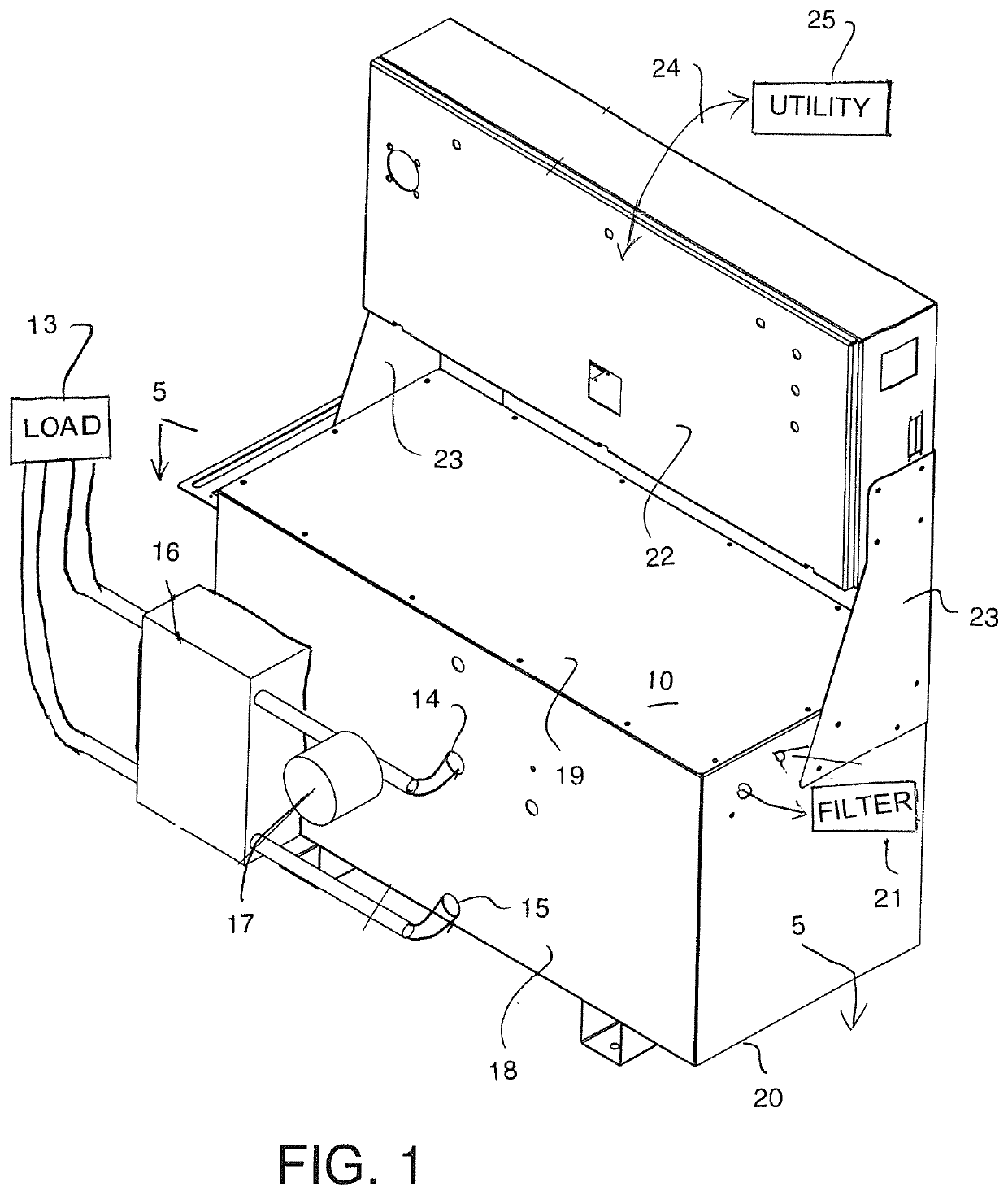
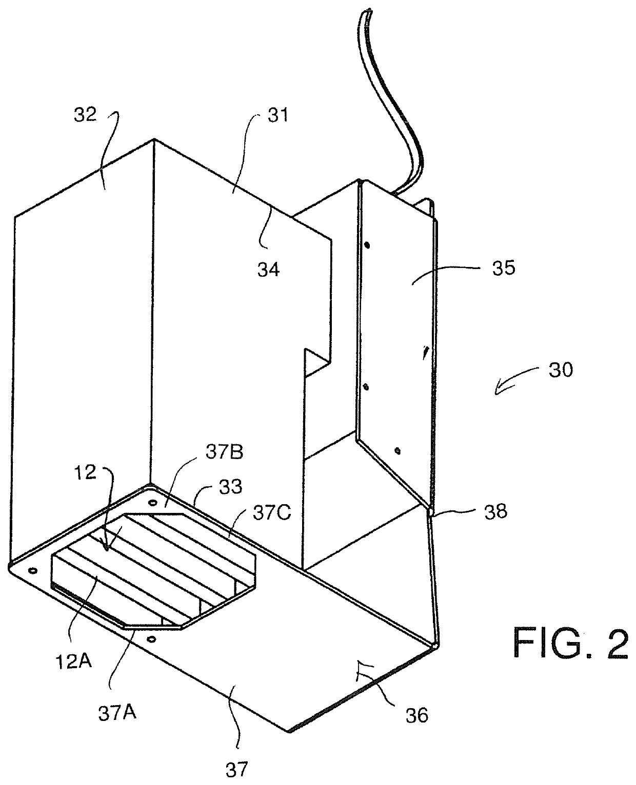
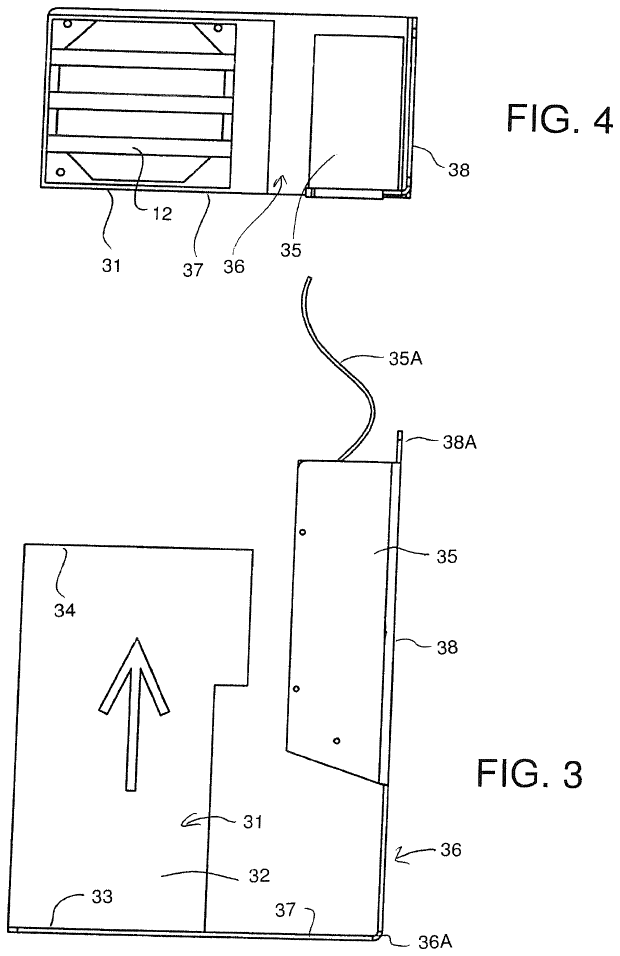
[0111]The arrangement here in provides a tank 10 containing a cooing liquid 11 for cooling a plurality of circuit boards 12 and transferring the heat therefrom to a load 13. The cooling liquid 11 is extracted from the tank through a discharge opening 14, passed through a heat exchanger 16 and returned to the tank through a return 15. A pump 17 is provided in the circuit through the heat exchanger to cause a flow in the liquid and to generate a low pressure at the return 15.

[0112]The tank comprises a rectangular body with four upstanding sides 18, a top cover 19 and a base 20. This forms a closed container where the tank has a head zone above the level 11A of the liquid and below the top 19 that also acts as an expansion area to accommodate fluid level fluctuations. The head zone is kept free from any moisture by an extraction and a filter system 21 to filter out any particulate material from the liquid as well as any moisture. The tank is thus sealed and vapour tight.

[0113]The liqui...


PUM


Abstract

Computer processing systems are cooled and the otherwise wasted heat is extracted for space heating by providing a cooling dielectric liquid in a tank which passes from a manifold at the bottom of the tank through an array of tubular housings each having open top and bottom ends and containing row of the circuit boards. The housings sit on a divider sheet which has arrays of openings aligned with the housings allowing the liquid to pass from the manifold under little or no pressure so that the liquid flows through the housings by convection and stratifies to generate a layer of heated liquid above the open tops of the housings which can be tapped off to a heat exchanger. A heat pump acts on the cooling liquid to transfer heat to a heat transfer liquid which can be further heated by a boiler and transferred to existing heat dissipating loads.

Description

[0001]This application is a continuation in part application of PCT Application PCT / CA2020 / 050600 filed May 5, 2020 which claims priority from Canadian application 3042519 filed May 7, 2019.[0002]This invention relates to an arrangement which includes a cooling tank to extract and utilize heat from the operation of the computer processing to maintain the unit cool and to enable the heat to be transferred and utilized in a separate heating operation.BACKGROUND OF THE INVENTION[0003]Currently the conventional way of cooling computers, servers or mining rigs is with air using high volume fans. This causes major problems with noise and dust control system equating to higher maintenance and set up costs.[0004]It is known that many computer processing systems generate significant quantities of heat so that cooling is required. Examples of immersive liquid cooling systems for computer processing are shown in U.S. Pat. No. 9,504,190 (Best) issued to Green Revolution Cooling Inc and other pa...

Claims


Application Information

Patent Timeline
Patent Type & Authority Applications(United States)
IPC IPC(8): G06F1/20H05K7/20
CPCG06F1/20G06F2200/201H05K7/20272H05K7/20236Y02B30/52H05K7/20772
Inventor GAUTHIER, STEPHANEMILLER, OSCARTORREALBA, HARTLEYLE WONG, ANNA
Owner GAUTHIER STEPHANE
Why Eureka
Try Eureka