
Air mover

a technology of air mover and air handle, which is applied in the direction of non-positive displacement fluid engines, radial flow pumps, non-positive displacement pumps, etc., can solve the problems of reducing the output flow rate of air mover, affecting the performance of air mover, and uneven weight distribution of conventional air mover. , to achieve the effect of uniform weight distribution of air mover, reduced noise of air mover, and easy carrying

Pending Publication Date: 2021-09-09
DELTA ELECTRONICS INC
View PDF11 Cites 0 Cited by
  • Summary
  • Abstract
  • Description
  • Claims
  • Application Information

AI Technical Summary

Benefits of technology

This patent describes an air mover that has a balanced weight distribution and is easy to carry. It is designed to decrease noise and increase output flow rate by simultaneously rotating two fans. The use of a co-axial motor and a spacer in the center of the mover also improves the uniformity of the weight distribution and the intake flow rates.

Problems solved by technology

This can cause the weight distribution of the conventional air mover to be uneven, and the air mover can be difficult to carry.
The great difference between the intake flow rates at the two inlets causes noise, and decreases the output flow rate of the air mover.

Method used


Image

  • Air mover
  • Air mover
  • Air mover

Examples


Embodiment Construction

[0035]The following description is of the best-contemplated mode of carrying out the invention. This description is made for the purpose of illustrating the general principles of the invention and should not be taken in a limiting sense. The scope of the invention is best determined by reference to the appended claims.

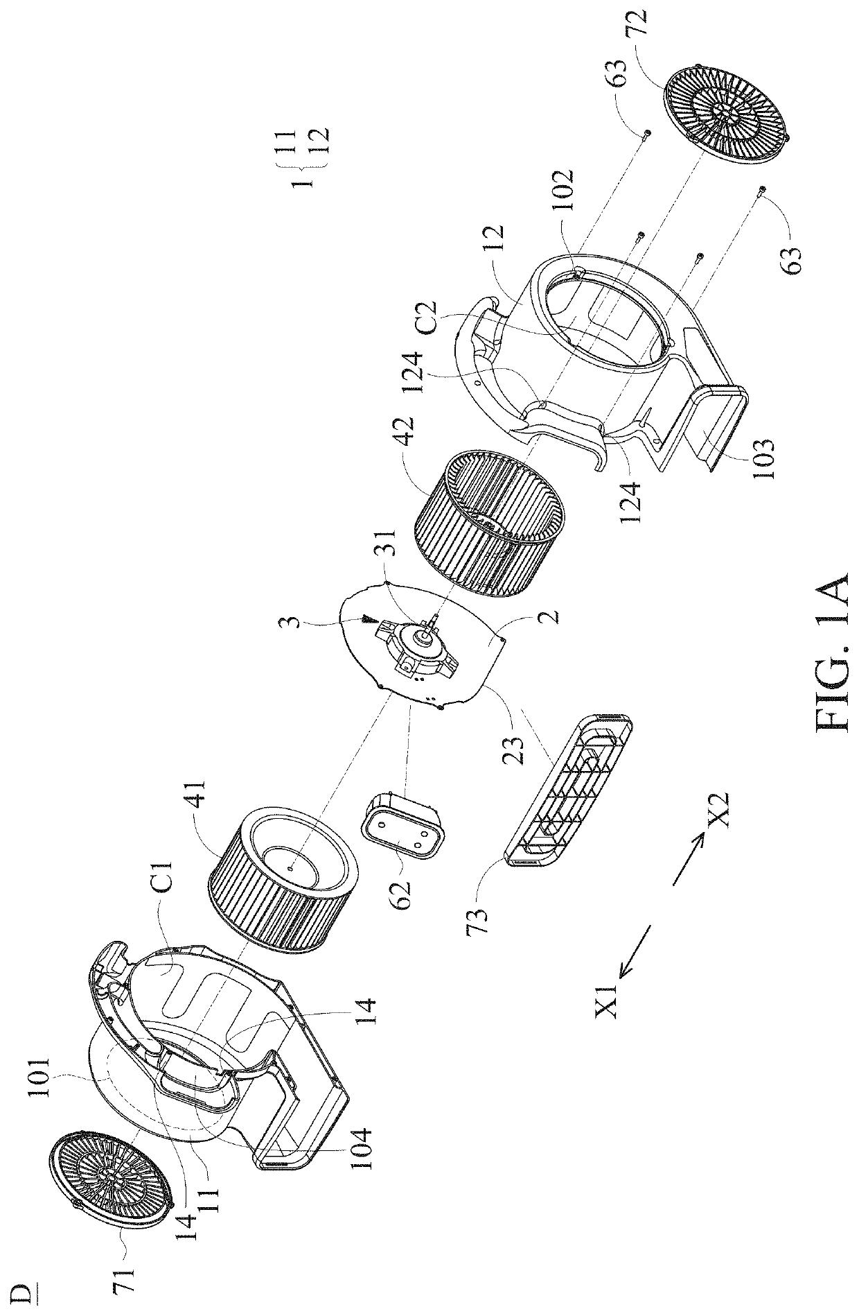
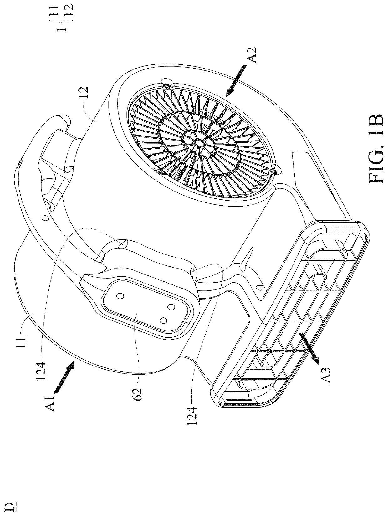
[0036]FIG. 1A is an exploded view of an air mover of an embodiment of the invention. FIG. 1B is an assembled view of the air mover of the embodiment of the invention. With reference to FIGS. 1A and 1B, the air mover D of the embodiment of the invention includes a housing 1, a spacer 2, a co-axial motor 3, a first fan 41 and a second fan 42. The housing 1 includes a first housing member 11 and a second housing member 12. A first inlet 101, a second inlet 102 and an outlet 103 are formed on the housing 1. The first inlet 101 is formed on the first housing member 11. The second inlet 102 is formed on the second housing member 12. The spacer 2 is disposed between the first...


PUM


Abstract

An air mover is provided. The air mover includes a housing, a spacer, a co-axial motor, a first fan and a second fan. The housing includes a first housing member and a second housing member. A first inlet, a second inlet and an outlet are formed on the housing. The first inlet is formed on the first housing member and the second inlet is formed on the second housing member. The spacer is disposed between the first housing member and the second housing member. The co-axial motor includes a shaft, wherein the co-axial motor is disposed on the spacer. The shaft includes a first free end and a second free end. The first free end extends in a first direction, and the second free end extends in a second direction.

Description

CROSS REFERENCE TO RELATED APPLICATIONS[0001]This application is a Continuation-In-Part of pending U.S. patent application Ser. No. 16 / 201,118, filed Nov. 27, 2018 and entitled “air mover”, which claims priority of China Patent Application No. 201810190509.5, filed on Mar. 8, 2018, the entirety of which is incorporated by reference herein.BACKGROUND OF THE INVENTIONField of the Invention[0002]The present invention relates to an air mover, and in particular to an air mover with two inlets.Description of the Related Art[0003]A conventional air mover (for example, a carpet drier) has a motor, a fan, two inlets, and an outlet. Conventionally, the motor is disposed on one side of the air mover. This can cause the weight distribution of the conventional air mover to be uneven, and the air mover can be difficult to carry. Additionally, the motor and the fan are adjacent to one side of the air mover, and the intake flow rates at the two inlets are different. The great difference between the...

Claims


Application Information

Patent Timeline
Patent Type & Authority Applications(United States)
IPC IPC(8): F04D17/16F04D25/06F04D25/16
CPCF04D17/16F04D25/166F04D25/0606F04D17/162F04D29/626F04D25/0693F04D29/424
Inventor CHEN, JHIH-JHONGCHEN, CHUN-WEILIN, WEN-HSIANG
Owner DELTA ELECTRONICS INC
Learn More