Fastening device for holding a sensor
- Summary
- Abstract
- Description
- Claims
- Application Information
AI Technical Summary
Benefits of technology
Problems solved by technology
Method used
Image
Examples
first embodiment
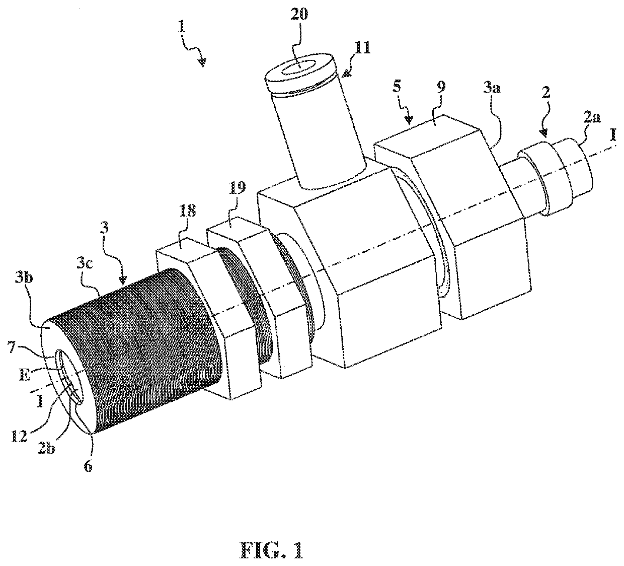
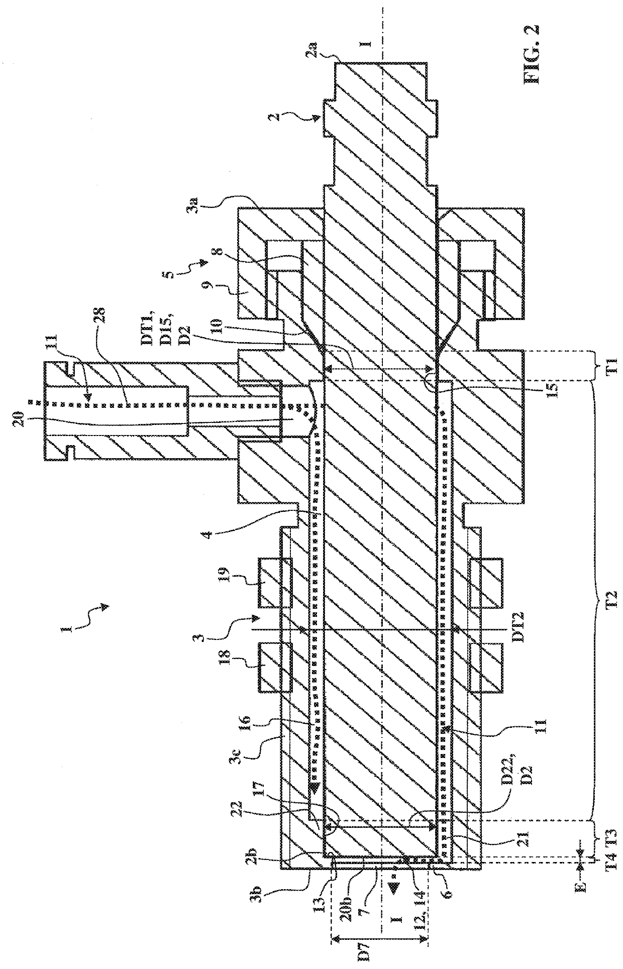
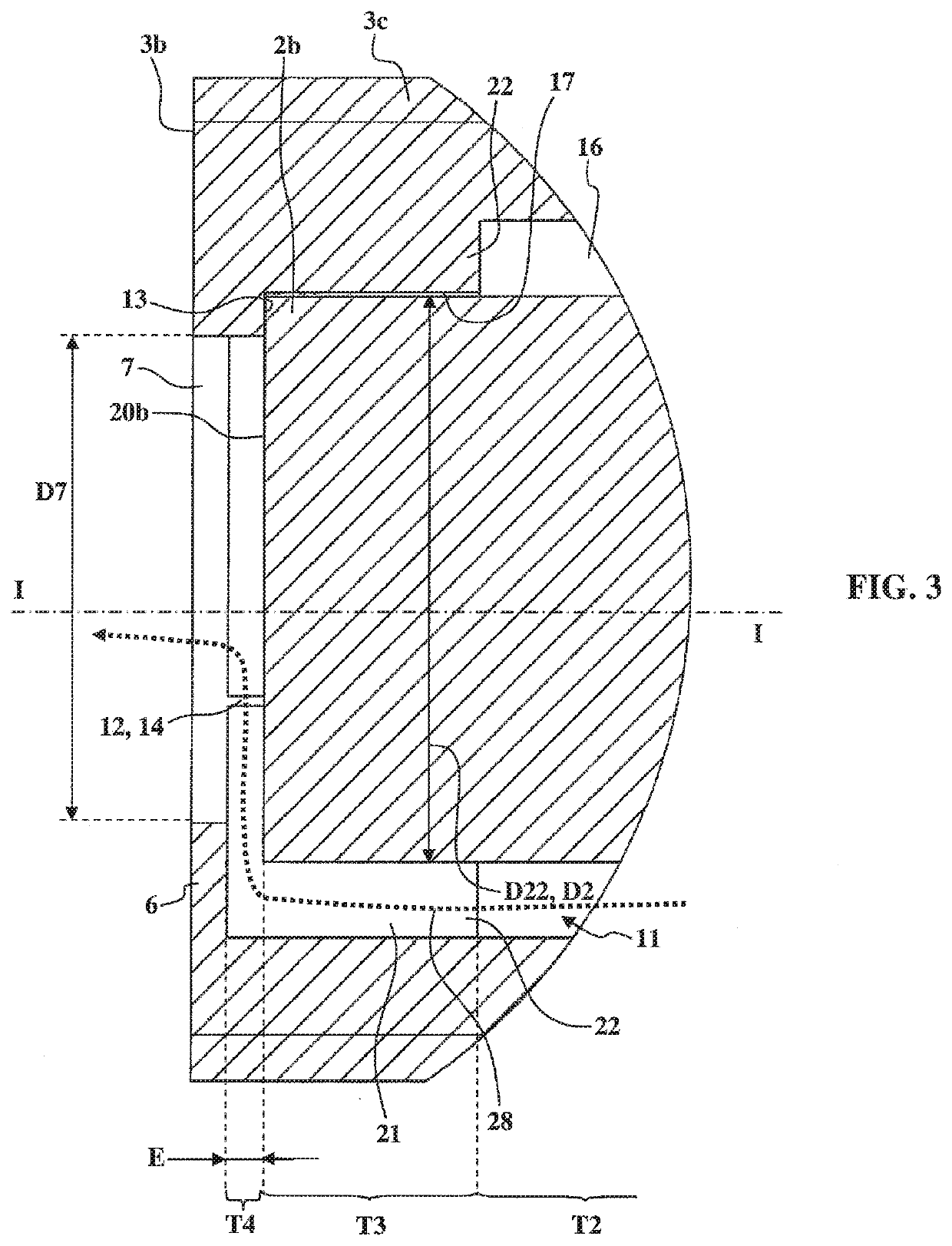
[0068]FIGS. 1 to 6 show a fastening device 1 according to the invention for holding a sensor 2. The sensor 2 has a cylindrical form limited by a proximal end 2a and a distal end 2b with a frontal end surface 20b.
[0069]The fastening device 1 comprises:[0070]a tubular body 3 extending along a median longitudinal axis I-I between a first end 3a and a second end 3b and comprising a longitudinal through passage 4 intended to receive said sensor 2;[0071]means 5 for axially immobilizing the sensor 2 in the longitudinal through passage 4.
[0072]The longitudinal axis I-I is median in that it is substantially located at the center of the longitudinal through passage 4.
[0073]The tubular body 3 comprises an external thread 3c so as to engage with a nut 18 and a lock nut 19 in order to be assembled through a wall of a machine tool or an automated line.
[0074]At the second end 3b of the tubular body 3, a flared portion 6 extends radially inwards (in other words by moving closer to the median longi...
second embodiment
[0105]In this second embodiment, a nut 25 engaging with the external thread 2c also can be used to limit the screwed penetration of the sensor 2 into the tubular body 3 in order to keep the distal end 2b of the sensor 2 at a predetermined longitudinal distance from said flared portion 6. The nut 25 thus can be used when the stop faces 13 define an excessively short minimum non-zero predetermined longitudinal distance from the flared portion 6 (or when it is preferable for a greater distance to be provided between the distal end 2b of the sensor 2 and the flared portion 6 than that which is provided by the stop faces 13).
[0106]As in the first embodiment, the second embodiment of a fastening device 1 comprises an external thread 3c of the tubular body 3 so as to engage with a nut 18 and a lock nut 19 so that it can be assembled through a wall of a machine tool or automated line.
[0107]The third embodiment of a fastening device 1 shown in FIGS. 8 and 9 is also very similar to the first ...
third embodiment
[0108]In the third embodiment, instead of an external thread 3c provided on the tubular body 3 in order for it to be fastened on a machine tool or automated line, the tubular body 3 comprises a radial flared portion 26, in which an oblong hole 27 is arranged that is intended to be traversed by one or more screws 30 intended to be screwed into the machine tool or automated line.
[0109]It must be noted that the tubular body 3 of the third embodiment of a fastening device 1 alternatively can comprise axial immobilization means 5 similar to those used in the first embodiment (with the conical ring 8, the nut 9 and the conical bearing surface 10) in order to receive sensors 2 without an external thread 2c on the external surface thereof.
[0110]The operation of the second and third embodiments of a fastening device 1 is very similar to that of the first embodiment.
[0111]One difference is that the penetration of the sensor 2 can be stopped before the distal end 2b comes into abutment against...
PUM
 Abstract
Description
Claims
Application Information
 - R&D
- Intellectual Property
- Life Sciences
- Materials
- Tech Scout
- Unparalleled Data Quality
- Higher Quality Content
- 60% Fewer Hallucinations
Browse by: Latest US Patents, China's latest patents, Technical Efficacy Thesaurus, Application Domain, Technology Topic, Popular Technical Reports.
© 2025 PatSnap. All rights reserved.Legal|Privacy policy|Modern Slavery Act Transparency Statement|Sitemap|About US| Contact US: help@patsnap.com


