
Method for machining the running surface of a rail

Pending Publication Date: 2021-10-07
MATE GMBH
View PDF0 Cites 0 Cited by
  • Summary
  • Abstract
  • Description
  • Claims
  • Application Information

AI Technical Summary

Benefits of technology

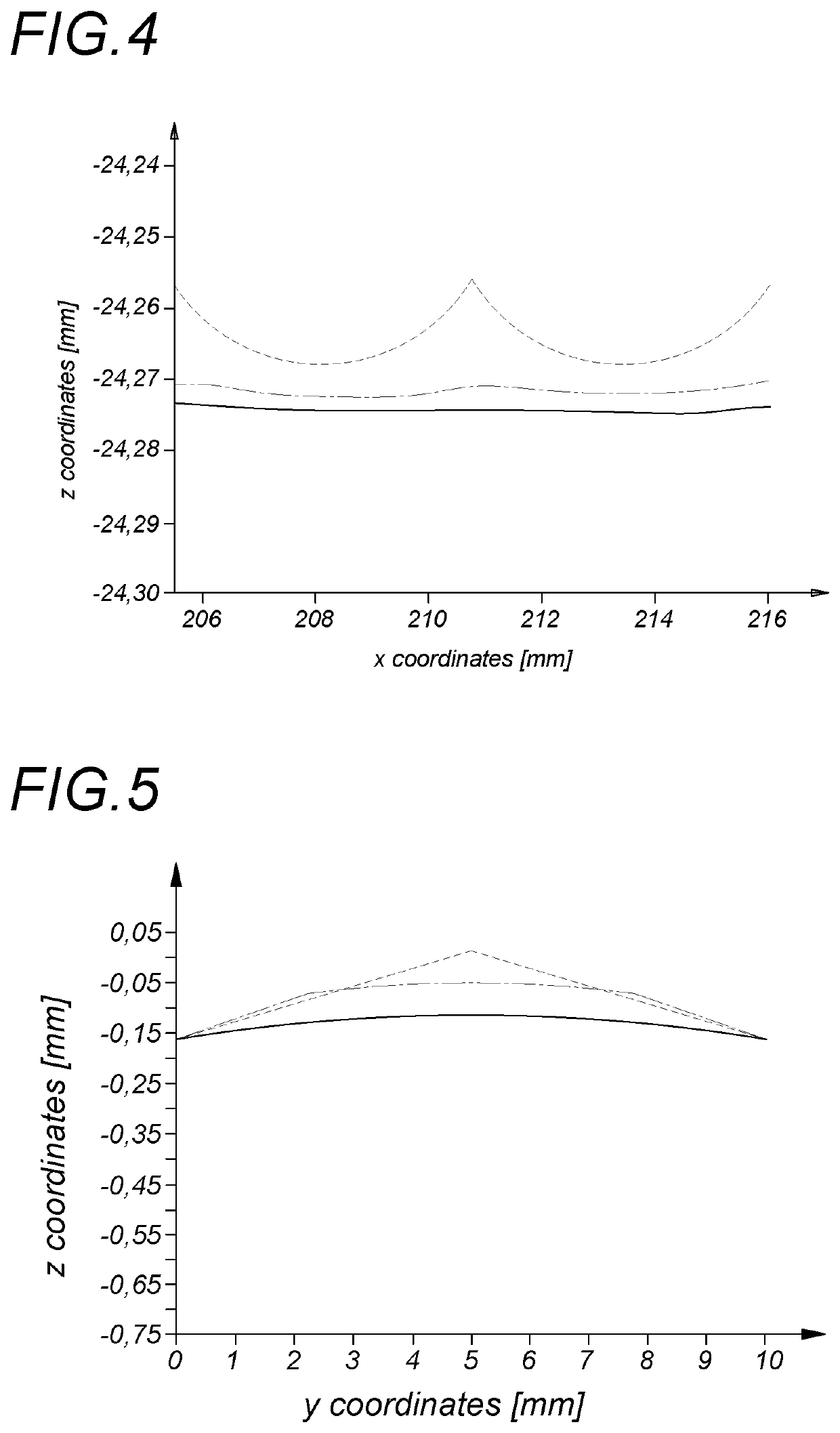
This patent describes a system for maintaining the surface quality of a rail by using rolling bodies that roll over the surface. These rolling bodies, which have a shape that matches the profile of the already reprofiled rail surface, exert a high pressure on the rail without removing material. The rolling process smooths out any unevenness or corrugations on the rail surface, reducing noise and vibrations. The system uses a slip of 0.001 to 20% between the rolling body and the rail to ensure optimal performance. Overall, this system improves the quality of the rail running surface and reduces the need for maintenance.

Problems solved by technology

Rails of rail vehicle tracks are subject to wear caused by contact forces between rails and the wheels of the rail vehicle rolling on them.
Corrugations are also caused by milling the rail head, for example.
Up to now, however, their use has only been possible on continuous track sections, whereas on track sections with rail interruptions, such as in the area of switches and crossings, reprofiling is often carried out with hand-held processing tools or smaller special devices.
Applied Acoustics 2016; 107: 10-18) that a periodic roughness on a rail surface, as it occurs after reprofiling the rail by milling or possibly also by grinding, leads to a significant increase in sound pressure when the rail is rolled over by a rail vehicle wheel, which is a high acoustic burden on the environment during rollover.
Also as a result of rail operation, local periodic irregularities of the running surface occur on the rail surfaces forming the running surfaces.
These irregularities cause vibrations and structure-borne noise when the wheels of the rail vehicle roll, which leads to noise pollution of the environment and noise and vibration nuisance for the passengers.

Method used


Image

  • Method for machining the running surface of a rail
  • Method for machining the running surface of a rail
  • Method for machining the running surface of a rail

Examples


Embodiment Construction

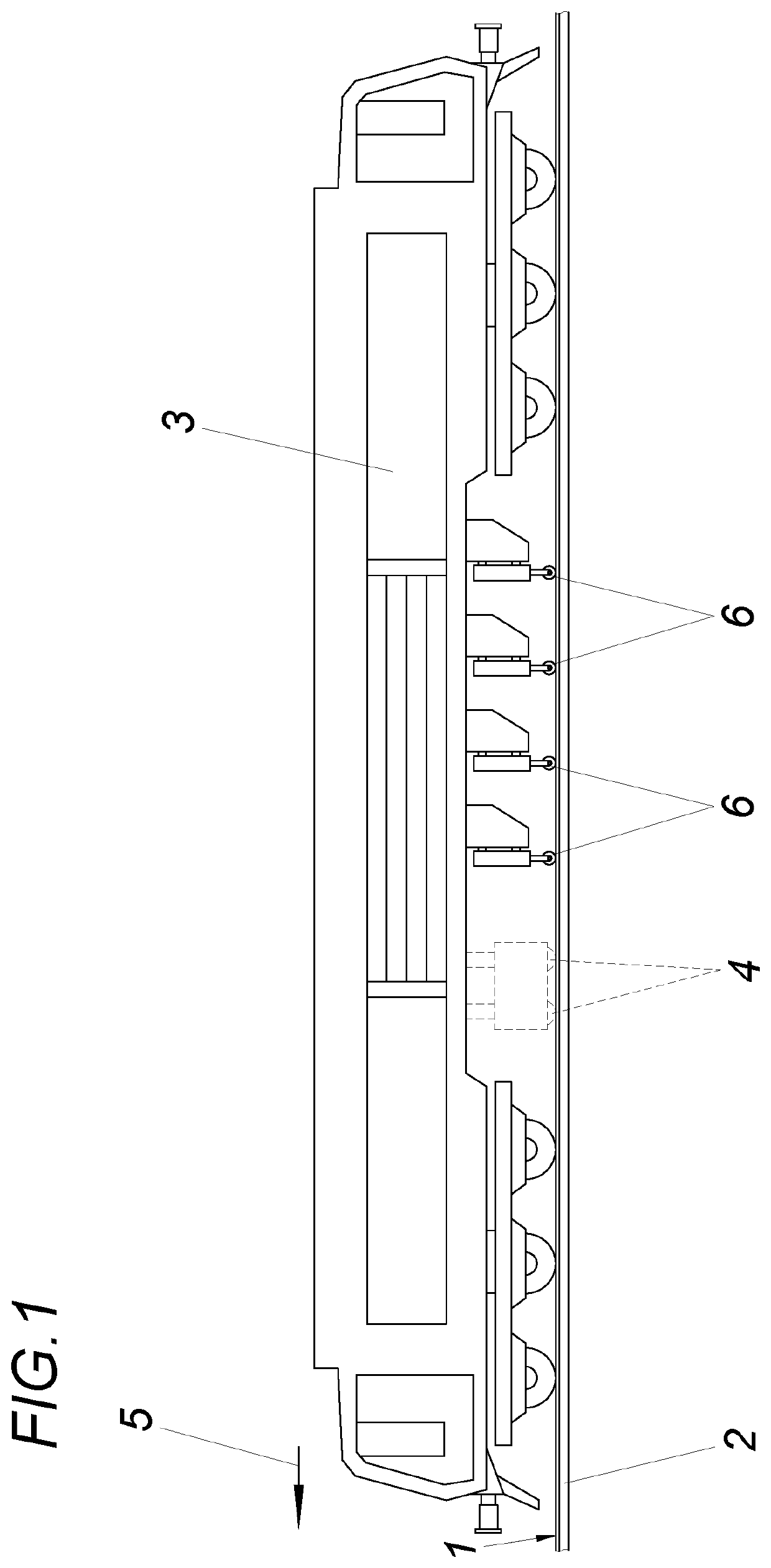
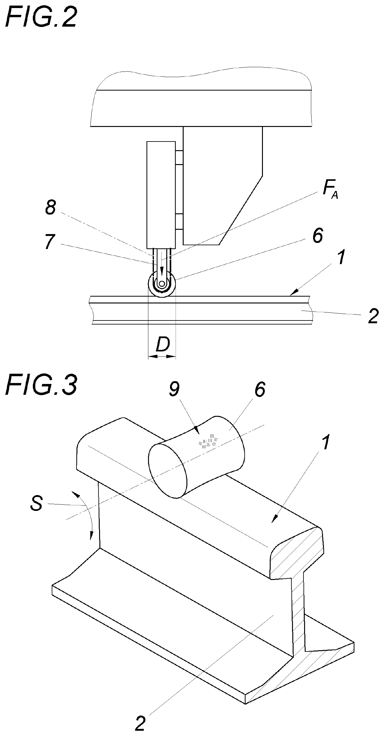
[0025]The device for machining the running surface 1 of a rail 2 with a rail-guided machining vehicle 3 includes at least one rotating, chip-removing shaping tool 4 which can be moved along the rail and pressed against its running surface 1. A rolling body 6 adapted to the shape-machined rail surface is arranged downstream of the shaping tool 4 in a working direction 5 extending in the longitudinal direction of the rail. The rolling body 6 may be moved along the rail 2 with the machining vehicle 3 for the purpose of leveling unevenness of the running surface 2 of the rail, with cold deformation of at least the running surface, in particular the shape-machined rail surface, of the rail 2, and can be pressed with an actuating drive 7 against the running surface 1 of the rail with a defined setting force FA. The machining vehicle 3 may, if necessary, consist of two or more carriages, which may operate independently, for example at least one for the shaping tool 4 and at least one for t...


PUM

PropertyMeasurementUnit
Fractionaaaaaaaaaa
Fractionaaaaaaaaaa
Pressureaaaaaaaaaa

Abstract

The system described herein relates to machining the running surface of a rail by means of at least one rotating, chip-removing shaping tool which can be moved along the rail and can be pressed at least against its running surface. In order to create advantageous design conditions, it is proposed that after the machining with the chip-removing shaping tool at least one rolling body which is adapted to the shape-machined rail surface is rolled over the rail, with cold deformation of the running surface of the rail, in order to level out unevenness of the running surface of the rail.

Description

FIELD OF THE INVENTION[0001]The system described herein relates to machining the running surface of a rail.DESCRIPTION OF THE PRIOR ART[0002]Rails of rail vehicle tracks are subject to wear caused by contact forces between rails and the wheels of the rail vehicle rolling on them. The undesired changes in the rail cross section caused by wear are subjected to a reprofiling process at regular intervals or as required by the circumstances in order to extend the service life. Preventive machining is also possible. Rail unevenness in the area of the rail head being driven over is divided into longitudinal waves (along the rail axis), corrugations (transverse to the rail axis) and finally roughness. Longitudinal waves are usually caused by the running operation. Corrugations are also caused by milling the rail head, for example. Roughness occurs especially during grinding of the rail head. Reprofiling of the rail head is mainly carried out with machining processes such as grinding, planin...

Claims


Application Information

Patent Timeline
IPC IPC(8): B24B19/00B23P9/02E01B31/13
CPCB24B19/004E01B31/13B23P9/02E01B31/12E01B31/15E01B31/17
Inventor KUBIN, WILHELMDAVES, WERNERECKER, WERNER
Owner MATE GMBH
Learn More