
Powertrain, vehicle and method of performing a gearshift in the powertrain

a technology of hybrid powertrains and powertrains, applied in mechanical equipment, transportation and packaging, gearshifting, etc., can solve the problems of low torque at the drive wheels, huge disadvantages for comfort, performance, emission control and fuel economy, etc., and achieve high energy efficiency and short time-saving

Active Publication Date: 2021-10-07
BRUDELI GREEN MOBILITY AS
View PDF0 Cites 2 Cited by
  • Summary
  • Abstract
  • Description
  • Claims
  • Application Information

AI Technical Summary

Benefits of technology

The powertrain described in this patent allows for control of torque levels in each of the clutches, and can increase the torque by speed difference. The use of electric motors allows for efficient boosting of torque for a short time. Overall, this invention improves the performance and energy efficiency of powertrains in vehicles.

Problems solved by technology

The torque in the gearbox will have to be zero at every gearshift and this also make the gearshift slow.
This is a huge disadvantage for comfort, performance, emission control and fuel economy.
A disadvantage of the AMT is that the torque at the drive wheels will go to zero each time a change of gear is done.
This is a major disadvantage for both comfort and acceleration performance (lost time for acceleration).
Furthermore, the loss of torque is also a challenge for control of the ICE to meet emission standards during gear shift.
To obtain what is essentially two gearboxes in one unit this transmission type is quite expensive and mechanically complex.
The addition of the electric motor E does not alleviate any of the disadvantages inherent in the respective type of transmission.
For instance, it may not be run as a serial hybrid during gearshift and this reduces the overall efficiency as well as increases the clutch wear.
Further, it is not possible to use the electric motor E actively to establish zero torque at the input shaft, as required to disengage / engage gear, nor may the electric motor accelerate the input shaft faster than the ICE.
These transmissions are known as feasible to make and control but have challenges in that the torque level transferred to the output shaft during gearshift is too low and / or that the wear in the clutch or clutches used during the gear shift is high.

Method used


Image

  • Powertrain, vehicle and method of performing a gearshift in the powertrain
  • Powertrain, vehicle and method of performing a gearshift in the powertrain
  • Powertrain, vehicle and method of performing a gearshift in the powertrain

Examples


Embodiment Construction

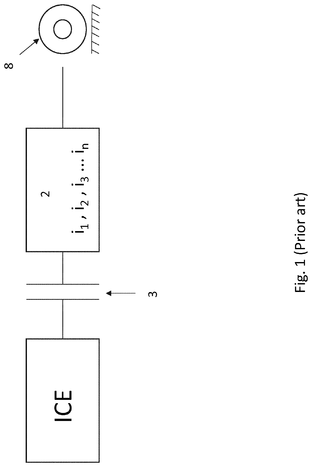
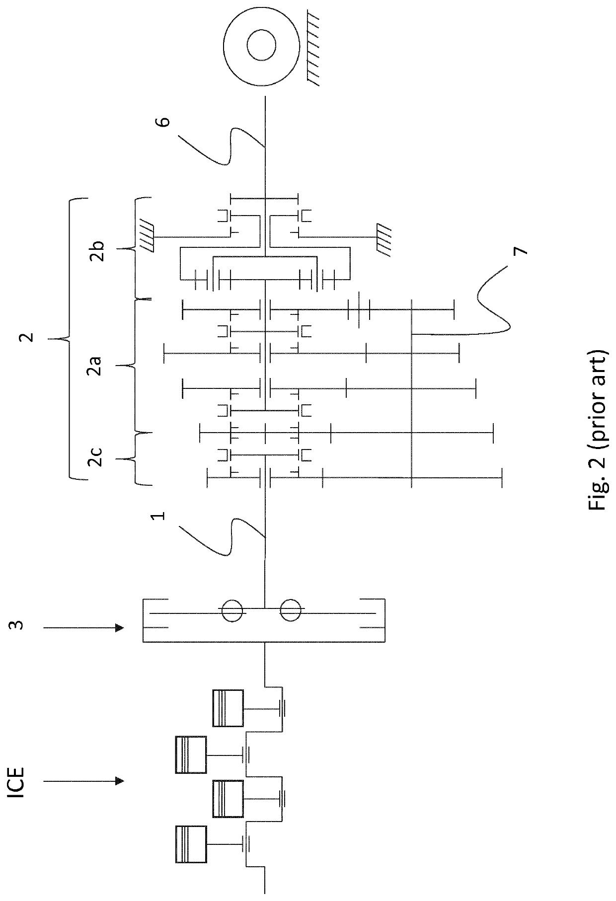
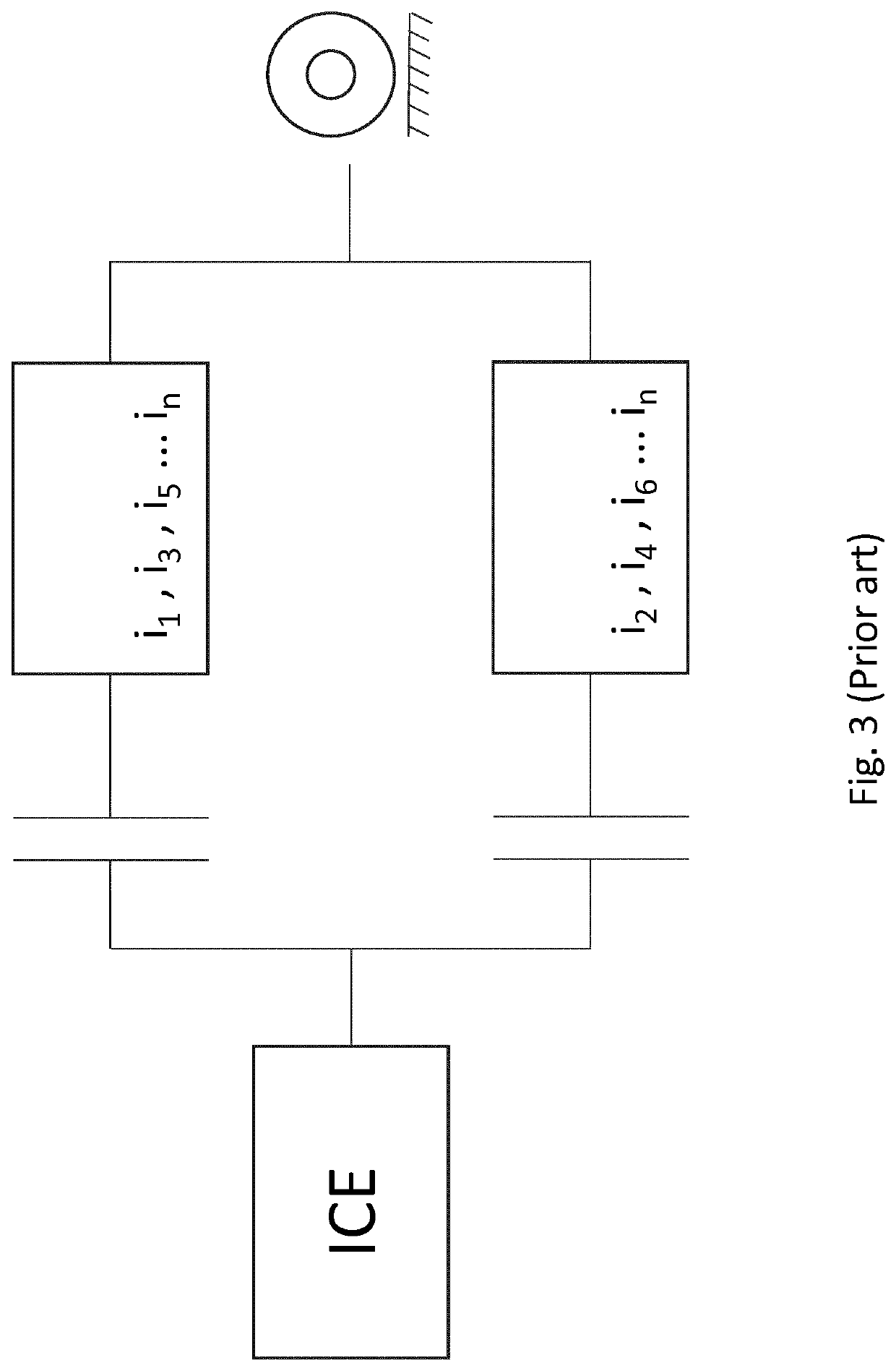
[0147]Based on the prior art described in the background section and shown in FIGS. 1-5, the applicant has developed a highly advantageous powertrain which is described in more detail by reference to FIGS. 6-21. Identical or similar technical features have been provided with the same reference number throughout the application.

[0148]An embodiment of a hybrid powertrain according to the invention is shown by use of a block diagram in FIG. 6. The powertrain comprises an ICE connected to an input shaft 1 (or input side) of a transmission 2 (or gearbox) via a main clutch 3, a first electric motor 4a, a second electric motor 4b, a first clutch 5a and a second clutch 5b. The first electric motor 4a is operatively connected to the input shaft 1, preferably via at least one gear ix (a first gear), and operatively connected to the second electric motor 4b via the first clutch 5a. The second electric motor 4b is operatively connected to an output shaft 6 (or output side) of the transmission 2...


PUM


Abstract

The present invention provides a powertrain comprising a transmission (2), a first electric motor (4a) and a second electric motor (4b), wherein the transmission comprises an input shaft (1) to which a source of mechanical power may be connected, an output shaft (6) and a gear assembly providing at least two different gear ratios that may be selected for transfer of mechanical power from the input shaft (1) to the output shaft (6), the first electric motor (4a) is connected to the input shaft (1), such that torque and rotation may be transferred between the first electric motor and the input shaft, and the second electric motor (4b) is connected to the input shaft (1) via a first clutch (5a), such that torque and rotation may be transferred between the second electric motor (4b) and the input shaft (1), and connected to the output shaft (6) via a second clutch (5b), such that torque and rotation may be transferred between the second electric motor (4b) and the output shaft (6), wherein the first electric motor (4a) is connected to the second electric motor (4b) via the first clutch (5a).

Description

FIELD OF THE INVENTION[0001]The present invention relates to hybrid and electric powertrains for vehicles.BACKGROUND[0002]The present invention provides a new and improved electric or hybrid transmission / powertrain system.[0003]There are many types of hybrid and electric powertrain systems. The two main types of hybrid systems are commonly termed parallel and serial hybrid systems.[0004]A simple version of the parallel hybrid system is a powertrain, wherein an electric motor is placed on one wheel-driving axle of a vehicle and an internal combustion engine (ICE) with transmission is placed on another wheel-driving axle of the vehicle. In another type of parallel hybrid powertrain an electric motor is attached to or integrated in the main gearbox.[0005]For cars, buses and trucks, hybrid systems are commonly made by using a transmission type that is a variant of the automatic transmission already used in a purely ICE-driven version of that vehicle type.[0006]For cars there are histori...

Claims


Application Information

Patent Timeline
Patent Type & Authority Applications(United States)
IPC IPC(8): B60K6/547B60K6/442B60K6/365F16H61/04
CPCB60K6/547B60K6/442F16H2061/0422F16H61/0403B60K6/365B60K6/36F16H37/046F16H2061/0429F16H2061/0433F16H3/089F16H2200/0043F16H2200/006Y02T10/62F16H2061/0425B60K6/50F16H3/72
Inventor BRUDELI, GEIR
Owner BRUDELI GREEN MOBILITY AS
Learn More