Methods, systems and apparatus for powering a vehicle

a technology for providing energy and vehicles, applied in the direction of capacitor collector combinations, machines/engines, vehicle sub-unit features, etc., can solve the problems of inconvenient or cumbersome wired and wireless stationary charging systems, many undesirable limitations, degradation of energy transfer efficiency or loss,

Active Publication Date: 2021-10-07
MACALUSO ANTHONY
View PDF11 Cites 22 Cited by
  • Summary
  • Abstract
  • Description
  • Claims
  • Application Information

AI Technical Summary

Benefits of technology

[0020]The present disclosure provides a system for providing power to a vehicle. The system may comprise: a driven mass configured to rotate in response to a kinetic energy of the vehicle, the driven mass coupled to a shaft such that rotation of the driven mass causes the shaft to rotate; a generator configured to generate an electrical output at a generator output terminal based on a mechanical input, the mechanical input mechanically coupled to the shaft such that rotation of the shaft causes the mechanical input to rotate; and a hypercapacitor. The hypercapacitor may comprise: at least one ultracapacitor electrically coupled to the generator output terminal, wherein the at least one ultracapacitor may be configured to: receive inbound en...

Problems solved by technology

However, such wired and wireless stationary charging systems may be inconvenient or cumbersome and have other drawbacks, such as degradation during energy transference, inefficiencies or losses, requiring a specific location for charging, and so forth.
Existing energy storage devices, such as batteries and capacitors, can be useful for storing energy but may have many undesirable limitations.
Additionally, although ultracapacitors/supercapacitors may be capable of withstanding more charge-discharge cycles than batteries without losing operational functionality, ultra...

Method used


Image

  • Methods, systems and apparatus for powering a vehicle
  • Methods, systems and apparatus for powering a vehicle
  • Methods, systems and apparatus for powering a vehicle

Examples


Embodiment Construction

[0063]The detailed description set forth below in connection with the appended drawings is intended as a description of exemplary embodiments and is not intended to represent the only embodiments in which the invention may be practiced. The term “exemplary” used throughout this description means “serving as an example, instance, or illustration,” and should not necessarily be construed as preferred or advantageous over other exemplary embodiments. The detailed description includes specific details for providing a thorough understanding of the exemplary embodiments. In some instances, some devices are shown in block diagram form.

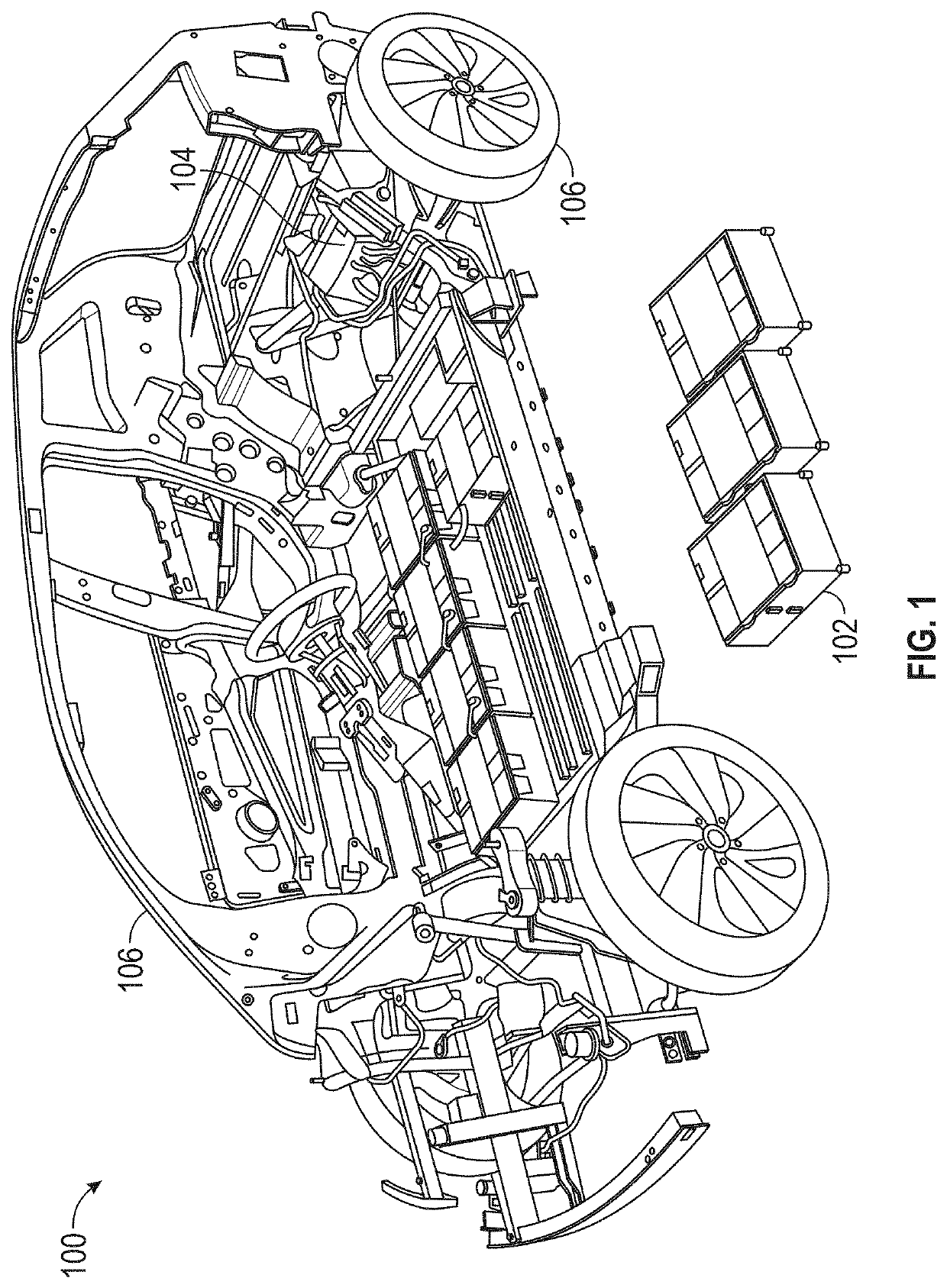
[0064]An electric vehicle (EV) is used herein to describe a vehicle that includes, as at least part of its locomotion capabilities, electrical energy derived from energy sources (e.g., one or more energy generation devices and energy storage devices, for example rechargeable electrochemical cells, capacitors, ultra-capacitors, other types of batteries, and ot...


PUM


Abstract

This application is directed to an apparatus for providing electrical charge to a vehicle. The apparatus comprises a driven mass configured to rotate in response to a kinetic energy of the vehicle, the driven mass coupled to a shaft, where rotation of the driven mass causes the shaft to rotate. The apparatus further comprises a hardware controller. The hardware controller identifies output power parameters for the vehicle and generate a control signal based on the identified output power parameters for the vehicle. The apparatus also comprises a generator that generates an electrical output based on a mechanical input and a conditioning circuit electrically coupled to the generator. The conditioning circuit receives the electrical output from the generator and the control signal from the hardware controller, generates a charge output based on the electrical output and the control signal, and conveys the charge output to the vehicle.

Description

CROSS REFERENCE TO RELATED APPLICATIONS[0001]This application claims benefit of priority to U.S. Provisional Patent Application No. 63 / 164,474, filed Mar. 22, 2021. This application is a continuation-in-part of U.S. patent application Ser. No. 17 / 141,518, filed Jan. 5, 2021, which is a continuation-in-part of U.S. patent application Ser. No. 16 / 847,538, filed Apr. 13, 2020, which claims benefit of priority and is related to U.S. Provisional Patent Application No. 62 / 858,902, filed Jun. 7, 2019, U.S. Provisional Patent Application No. 62 / 883,523, filed Aug. 6, 2019, and U.S. Provisional Patent Application No. 62 / 967,406, filed Jan. 29, 2020. This application is also filed concurrently with a U.S. nonprovisional application entitled “HYPERCAPACITOR.” The disclosure of each of the aforementioned applications is incorporated herein in its entirety for all purposes.BACKGROUNDField of the Disclosure[0002]The present disclosure relates generally to providing energy for a vehicle powered, a...

Claims


Application Information

Patent Timeline
IPC IPC(8): H01G11/08B60K1/04B60L53/14B60L50/40B60L53/24
CPCH01G11/08B60K1/04B60L53/24B60L50/40B60L53/14B60K1/00B60K25/08B60K2001/0438B60L8/00B60L50/90B60L53/16B60L53/18B60L53/32H02J7/32H02K7/025H02K7/1004H02K7/116H02K7/1846H02K2213/03Y02E60/16Y02T10/62Y02T10/64Y02T10/70Y02T10/7072Y02T90/12Y02T90/14Y02T90/16H01G11/10B60K2001/0466B60Y2400/114H02J7/345H02J2310/40H02J2207/50F03G3/08Y02T10/92B60L53/00B60K6/28
Inventor MACALUSO, ANTHONY
Owner MACALUSO ANTHONY
Why Eureka
Try Eureka