
System and method for optimized production of hydrocarbons from shale oil reservoirs via cyclic injection

Pending Publication Date: 2021-10-14
SHALE INGENUITY LLC
View PDF7 Cites 0 Cited by
  • Summary
  • Abstract
  • Description
  • Claims
  • Application Information

AI Technical Summary

Benefits of technology

The patent describes a method and apparatus for increasing oil recovery from shale reservoirs by injecting natural gas components in the liquid state into the wellbore at high pressures to create new fractures and displacing the injectant into these fractures, resulting in the recovery of oil from the exposed areas of the formation. A proppant material can be added to the injectant to keep the fractures open and allow oil and injectant to flow from them to the wellbore. The method can involve injecting the hydrocarbon-containing fluids in the liquid and gaseous state, and compositional adjustments can be made to optimize oil recovery. The process can also involve the use of microseismic equipment, formation resistivity measurement equipment, or surface deformation equipment to measure the movement of fluid or rock due to the injection. Reservoir simulation modeling can be used to better analyze the process.

Problems solved by technology

Permeability of these shales is very low, and as a result the recovery of the oil and gas therefrom is limited in most cases to only 3-10 percent.
Carbon dioxide is used in the process due to its high miscibility in crude oil.
Because the permeability of these shale oil and gas reservoirs is much lower than 1 millidarcy, primary production via pressure depletion results in the recovery of only a few percent of the oil in place.
Production from these wells is characterized by high initial flow rates of oil and gas, and a rapid decline in production over the first year, followed by a hyperbolic decline thereafter.
However, the method does not provide for optimizing the composition of the injection gases so as to maximize the recovery of the oil remaining in the shale oil reservoir during the cyclic injection process, nor the system required to enable the optimization process.

Method used


Image

  • System and method for optimized production of hydrocarbons from shale oil reservoirs via cyclic injection
  • System and method for optimized production of hydrocarbons from shale oil reservoirs via cyclic injection
  • System and method for optimized production of hydrocarbons from shale oil reservoirs via cyclic injection

Examples


Embodiment Construction

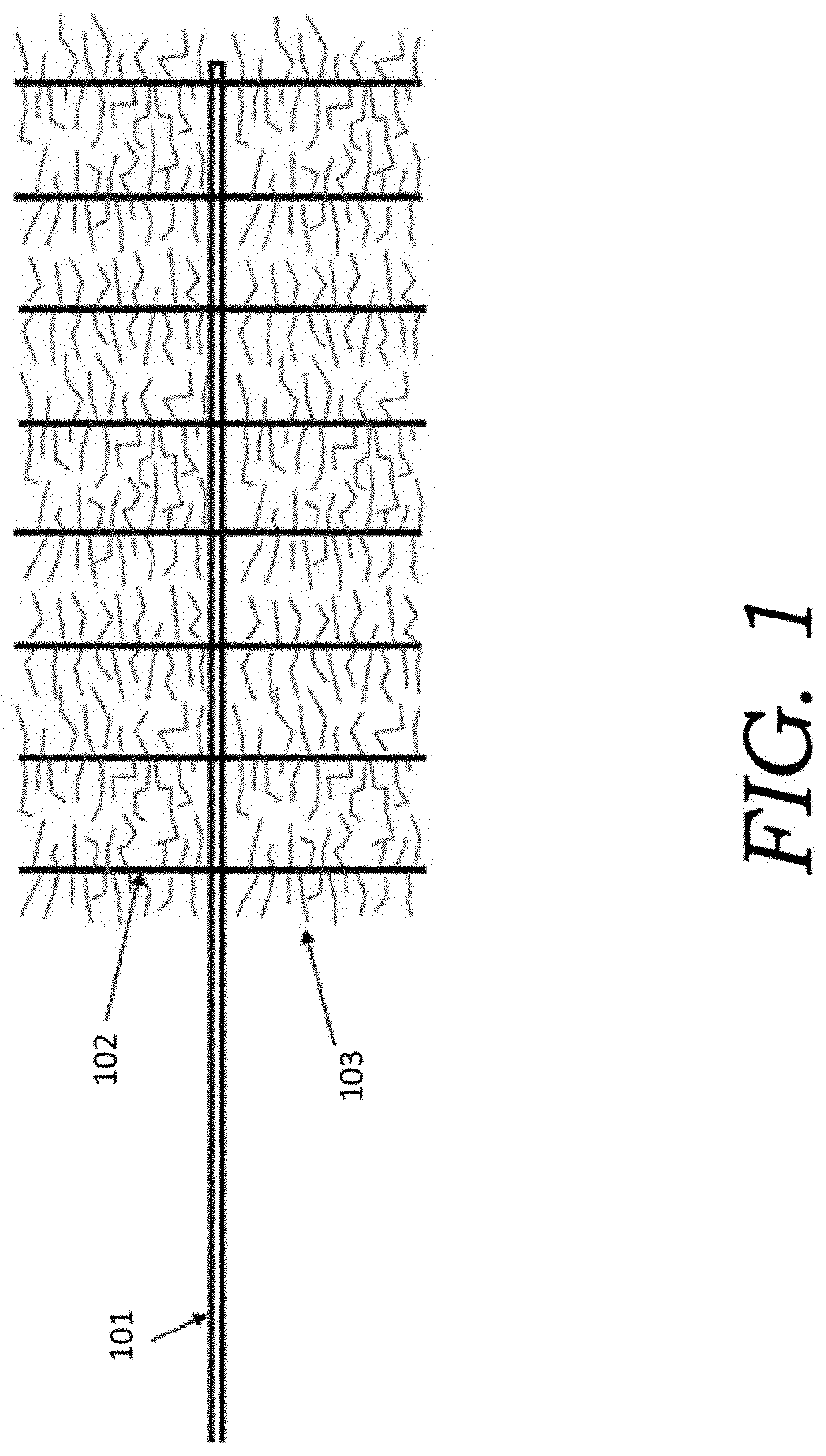
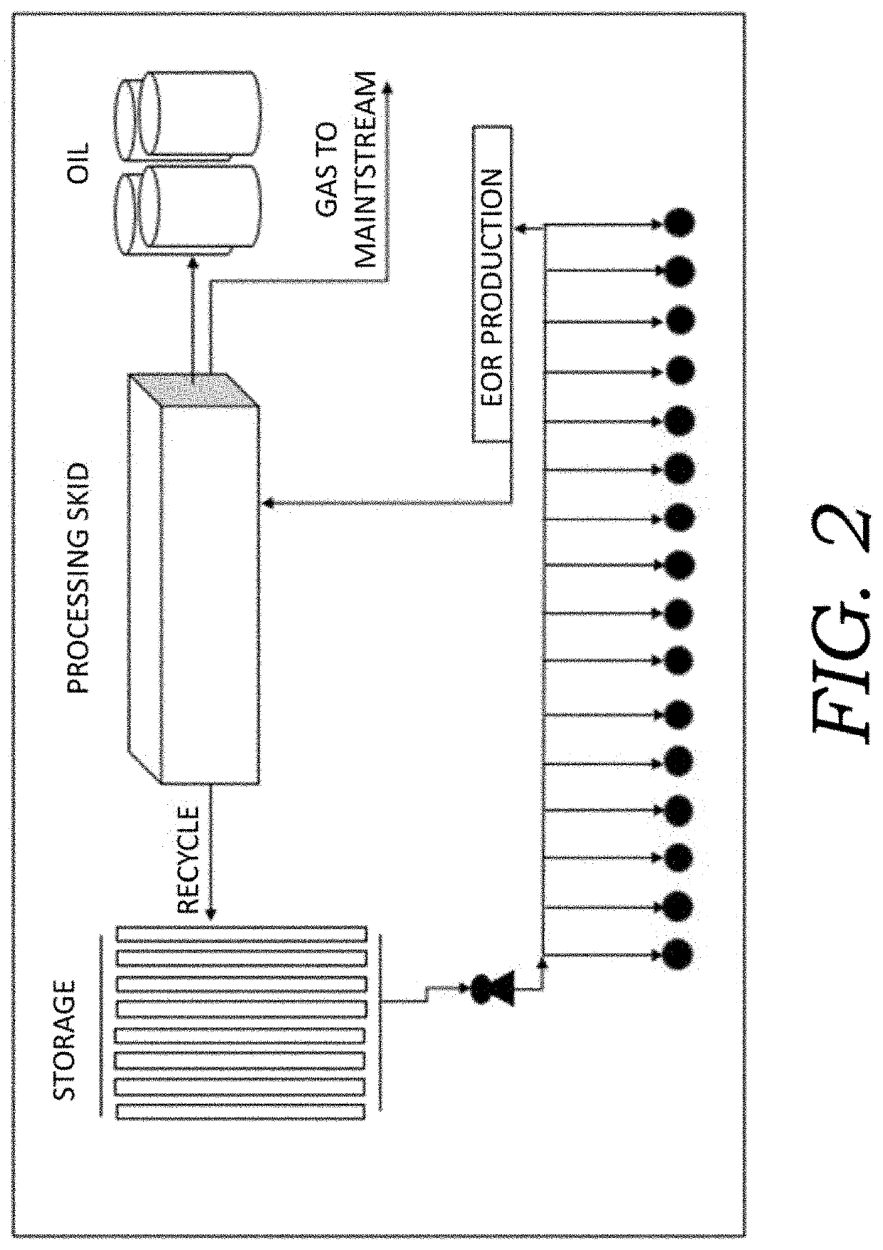
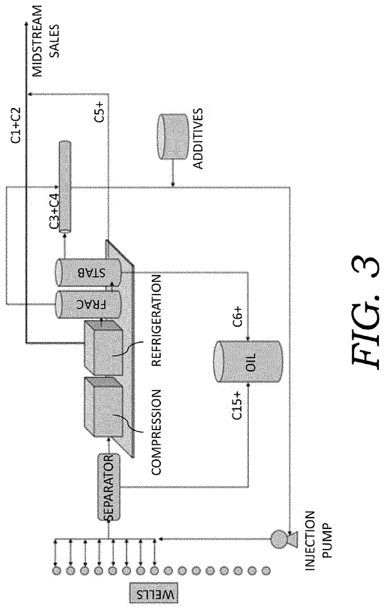
[0043]The present invention generally relates to the production of liquid oil from shale reservoirs. More particularly, the present disclosure relates to an apparatus and methods and processes of its design and operation for the optimization of liquid oil production by cyclic injection of hydrocarbon-containing liquids to pressures exceeding the pressure at which the producing formation begins to fracture, exposing additional formation surface area to the injectant; and their recovery, adjustment and reinjection to achieve an improved and optimal oil recovery.

[0044]Recovery of oil via cyclic injection and production occurs from surface areas of a shale oil formation that are contacted by the injection of the hydrocarbon-containing liquids. These surface areas of contact are generated by the hydraulic fracture stimulation treatment conducted in the well upon its initial completion. During the hydraulic fracture stimulation treatment, a proppant material, such as sand, is pumped with ...


PUM


Abstract

Method for enabling the optimized production of hydrocarbons from shale oil reservoirs via cyclic injection to reservoir pressures that exceed the formation fracture pressure to achieve an improved and optimal recovery of oil. The method determines and optimizes the composition of injected fluids to be injected, the rate, pressure and duration of injection, the production rate and pressure of produced fluids; determines and utilizes the optimum number of injection and production cycles; and the amount of soaking time; and determines the equipment design and operating characteristics to provide for the optimized injection of injection fluids, and the separation of produced fluids for both reinjection and delivery to sales or storage.

Description

RELATED PATENTS AND PATENT APPLICATIONS[0001]This application claims priority to U.S. Provisional Patent Application Ser. No. 63 / 008,322, filed Apr. 10, 2020, entitled “System And Method For Optimized Production Of Hydrocarbons From Shale Oil Reservoirs Via Cyclic Injection.” This patent application is commonly assigned to the Assignee of the present invention and is incorporated herein by reference in its entirety for all purposes.[0002]The present invention generally relates to the production of liquid oil from shale reservoirs. More particularly, the present disclosure relates to an apparatus and method for enabling the optimization of liquid oil production by cyclic injection of hydrocarbon-containing liquids and their recovery, adjustment and reinjection to achieve an improved and optimal oil recovery.FIELD OF INVENTION[0003]The present invention generally relates to the production of liquid oil from shale reservoirs. More particularly, the present disclosure relates to an appa...

Claims


Application Information

Patent Timeline
IPC IPC(8): E21B43/25E21B43/16E21B43/26E21B43/40E21B49/00
CPCE21B43/255E21B43/168E21B43/2605E21B2200/20E21B43/40E21B49/00E21B43/2607
Inventor DOWNEY, ROBERT A.
Owner SHALE INGENUITY LLC
Learn More